Configuration Options
This is a comprehensive list of configuration options understood by the Smoothie firmware.
Some advanced options are omitted from this list and are not recommended for general use.
Getting More Information
If you want more information about a given module, how it works and how to configure it, (and any advanced options that are not in this list) you can refer to that module’s specific documentation page.
For information on pin options and electrical settings (pull up, pull down, open drain, etc.), please refer to configuring-smoothie.
System & General Settings
The system configuration controls core firmware behavior including step generation frequency, USB modes, LED indicators, and communication interfaces. These settings affect fundamental system operation and should be configured before other modules. For complete documentation, see the system settings section.
| V1 Setting | V2 Setting | Description |
|---|---|---|
|
Maximum step generation frequency in Hertz — the theoretical ceiling at which the firmware can generate step pulses across all motors, based on MCU speed and firmware overhead. Actual achievable speed depends on this frequency together with microstepping and steps per millimeter.
Higher frequencies allow faster machine movement but need more CPU processing power. |
||
|
Duration of the step pulse sent to stepper drivers, in microseconds — how long the STEP signal stays high before returning low. Increase this if stepper motors are missing steps, behaving erratically, or making unusual noises. Most modern drivers work fine with 1µs pulses; older drivers may need 2-3µs. Some external drivers specify a minimum pulse width in their datasheet — check it if unsure. |
||
|
Enable DFU (Device Firmware Update) mode for developers. When enabled, the board can enter DFU mode for low-level firmware flashing via USB without needing the SD card bootloader. Primarily for firmware developers and advanced users who need to flash firmware directly to the microcontroller's internal flash memory. Disabled by default for safety, to prevent accidental bricking of the board. Only enable if you understand the risks and need direct flash access. |
||
|
Enable Mass Storage Class mode, which allows the SD card to be accessed as a USB drive when connected to a computer — you can drag and drop files directly to the board's SD card without removing it. NOTE: the V1 setting is inverted (msd_disable) and requires special firmware to function, while V2 uses standard msc_enable logic and is enabled by default. Disabling this can improve USB serial reliability on some systems. |
||
| — |
LED that flashes when the board is in Mass Storage Class mode and the SD card is being accessed — provides visual feedback that the SD card is being read or written via USB, warning you not to disconnect the cable during file operations. The LED flashes rapidly during active transfers and stays off when no transfers are occurring. Only used when msc_enable is true. |
|
|
Optional secondary play LED pin that mirrors the main play LED state. In V1, this setting disables the play LED; in V2, it specifies an auxiliary LED pin. Useful for lighted kill buttons, external status indicators, or remote control panels that need to show when the machine is running (playing G-code from SD card) or idle. The LED turns on when actively executing G-code and turns off when idle or paused. |
||
| — |
Global enable pin for all FETs (Field Effect Transistors) controlling heaters, fans, and other high-power outputs. This is typically a NOT-enable signal (active low) that controls power to all output FETs — when the pin is high (disabled), all FET outputs are turned off as a safety measure. Both this pin and fets_power_enable_pin must be in the correct state for FETs to operate, providing hardware-level safety control over all high-power outputs. |
|
| — |
Global power enable pin for FETs — typically an active-high enable signal that controls the power supply to all FET circuits. On the Prime board, this controls a separate power rail that supplies the FET drivers. Both this pin and fets_enable_pin must be in the correct state for FETs to operate. This dual-control approach provides enhanced safety by requiring two independent signals for high-power output operation, preventing accidental activation. |
|
| — |
Automatically flash firmware from a flashme.bin file if present on the SD card at boot. When enabled, the system checks for a valid flashme.bin file on startup and automatically performs the firmware update if found; the file is renamed to flashme.old after successful flashing. Disable this if you want manual control over firmware updates or if automatic updates interfere with your workflow. Useful for automated deployment in production environments. |
|
|
Enables GRBL compatibility mode for CNC applications. When enabled, the firmware responds with GRBL-style status messages and command acknowledgments, making it compatible with GRBL-based software and sender applications like bCNC, Universal G-code Sender, and similar CNC control programs. This mode changes how certain G-codes are interpreted and how responses are formatted to match GRBL's behavior. Essential for using GRBL-specific features in CAM software. |
||
| — |
Enables config-override functionality, allowing runtime configuration changes to be saved with Unlike v1, where the override file was always active if present, v2 requires this feature to be explicitly enabled. Useful for storing calibration values, PID tuning, and other runtime-adjustable parameters that should persist across reboots. |
|
|
Enable a second USB serial console port for simultaneous connections. When enabled, the board presents two USB serial interfaces (composite device), allowing both a host application (like Pronterface) and a terminal to be connected at the same time. Both ports share the same USB connection but appear as separate COM/tty devices to the host operating system. Useful for debugging while running a print job, or for having both manual control and automated monitoring. |
||
|
UART communication speed in bits per second — must match the baudrate configured on the connected device. Higher baudrates allow faster communication and G-code streaming. Common values are 9600, 19200, 38400, 57600, and 115200. The V1 setting applies to UART0 (primary serial port), while V2 allows per-UART configuration. Note that higher baudrates may be less reliable over long cable runs or in electrically noisy environments. |
||
| — |
Number of data bits per character transmitted over UART. Standard serial communication uses 8 bits, which can represent 256 different values (0-255) per character. This should match the configuration of the device you're communicating with. Some older systems may use 7-bit communication, but this is rare in modern applications. |
|
| — |
UART hardware channel number to use. Different boards support different numbers of UART channels; channel 0 is typically the primary debug UART. The Smoothieboard supports multiple UART channels with different pin assignments. Consult your board's pinout documentation to determine which channel corresponds to which physical pins. |
|
| — |
Use the UART as a console interface for sending and receiving commands, versus using it for raw data transmission. When true, the UART behaves like the USB serial console, accepting G-code commands and providing response messages. When false, it can be used for raw binary communication or specialized protocols. |
|
| — |
Enable UART console for serial communication over hardware UART pins. When enabled, the board can communicate via a dedicated UART channel in addition to USB serial, allowing simultaneous connections or communication with other microcontrollers. Useful for interfacing with external devices like touchscreens, Raspberry Pi, or other embedded systems. |
|
| — |
Parity checking mode for error detection. Must match the parity setting of the connected device.
Parity checking is less common in modern short-distance serial communication but can be useful for noisy environments. |
|
| — |
Number of stop bits appended after each character. Stop bits provide synchronization time between characters, allowing the receiver to prepare for the next character. Most modern serial communication uses 1 stop bit, though 2 stop bits can be used for slower or noisier communication links. Must match the configuration of the connected device. |
|
| — |
Sets the PWM frequency for hardware PWM timer 1 in Hertz. V2 uses two hardware PWM timers (PWM1 and PWM2), each with 4 channels; all channels on the same timer share the same frequency. Typical values range from 1000Hz (for heaters) to 20000Hz (for fans and motor control). Lower frequencies reduce electromagnetic interference but may cause audible noise in some devices. Higher frequencies are quieter but may not be compatible with all hardware. |
|
| — |
Sets the PWM frequency for hardware PWM timer 2 in Hertz. V2 uses two hardware PWM timers (PWM1 and PWM2), each with 4 channels; all channels on the same timer share the same frequency. Typical values range from 1000Hz (for heaters) to 20000Hz (for fans and motor control). Having two independent timers allows using different frequencies for different output types (e.g., 1kHz for heaters on PWM1, 20kHz for fans on PWM2). |
Motion Control
The Motion Control module is the heart of Smoothie’s kinematic system. It handles coordinate transformation, acceleration planning, and real-time motion execution. This module converts G-code commands into precise stepper motor movements based on your machine’s kinematics (cartesian, delta, CoreXY, etc.). For complete documentation, see the Motion Control page.
| V1 Setting | V2 Setting | Description |
|---|---|---|
|
Default rate for Overridden by the first |
||
| Default rate for |
||
|
Arcs are cut into segments (lines) — this setting is the maximum error allowed for the line segments that divide an arc. Controls arc segmentation quality versus performance, using adaptive segment sizing. |
||
|
Lines can be cut into segments — generally not useful with cartesian-coordinate robots — this setting sets the maximum length of any given segment; segments longer than this are cut into several shorter ones. When set to Essential for delta robots to maintain accuracy. |
||
|
Instead of cutting lines into segments based on distance, cuts them based on time: segments are sized so that Smoothie executes about Mostly useful with When set to a non-zero value, overrides |
||
|
Defines how many blocks (line segments) are stored in RAM for look-ahead acceleration calculation. Do not change this unless you know exactly what you are doing. Increasing the queue size uses more RAM and can cause Smoothie to run out of memory, depending on your configuration and how much the rest of your modules already use. Larger values allow better speed optimization through corners but consume more memory. |
||
|
Acceleration, in millimetres/second/second — the rate at which the machine accelerates and decelerates during moves. Higher values make the machine faster and shakier; lower values make it slower and sturdier. Generally proportional to the weight of the tool being moved. Can be overridden using |
||
|
Specific acceleration for Z axis movements. When set to a valid number, overrides the default When set to The Z axis often benefits from lower acceleration than XY, to prevent layer artifacts. |
||
|
Acceleration in millimetres/second/second for the alpha actuator (X axis on cartesian). Do not set on deltas. When set to a valid number, overrides the global default |
||
|
Acceleration in millimetres/second/second for the beta actuator (Y axis on cartesian). Do not set on deltas. When set to a valid number, overrides the global default |
||
|
Acceleration in millimetres/second/second for the gamma actuator (Z axis on cartesian). Do not set on deltas. When set to a valid number, overrides the global default |
||
|
Similar to the old "max_jerk", in millimeters — defines how much the machine slows down when decelerating, proportional to the vector angle of the change in direction. See here and here. Lower values mean being more careful; higher values mean being faster with more jerk. Replaces traditional "jerk" settings with a more mathematically sound approach. |
||
|
Junction deviation for Z only moves.
Do not set this value if you use a delta arm solution. |
||
|
Sets the minimum planner speed, in millimetres/sec — the lowest speed the planner will ever set a move to. Not generally useful. Prevents extremely slow movements that could cause stepper stalls or uneven extrusion in 3D printing. When set to |
||
|
Duration of step pulses to the stepper motor drivers, in microseconds. The actual step pulse is generally 2µs above this value (so Setting this over about 8µs will cause severe issues with step generation. Some stepper drivers require a minimum pulse width to reliably register steps — check your driver datasheet for its "Step Pulse Width" specification and set at least 2× that minimum for reliability. Use |
||
|
Base frequency for stepping — higher values give smoother movement. Do not modify unless you know exactly what you are doing; This is the fundamental rate at which the step generation interrupt runs — all step generation is derived from it through integer division. The maximum step rate per motor equals Higher frequencies increase interrupt load and may affect response time for other operations. |
Actuators (Stepper Motors)
Actuators define the physical stepper motors that move your machine’s axes. Each actuator has configuration for pin assignments, steps per millimeter, maximum speeds, microstepping, and optional features like motor reversal and slaving for dual-motor setups. Proper actuator configuration is essential for accurate motion control.
| V1 Setting | V2 Setting | Description |
|---|---|---|
| — |
Enables real-time checking of TMC driver error status bits, including overtemperature, short circuit, and open load conditions. When enabled, the firmware periodically reads driver status registers and reports any detected errors to the console. |
|
| — |
Determines whether the system immediately enters HALT state when a TMC driver reports an error condition. When enabled, any driver alarm — overtemperature, short circuit, or open load — causes the system to stop all operations immediately. |
|
| — |
Defines a global enable pin that controls power to all stepper motors simultaneously — a master enable/disable switch for all motors. On Prime board with TMC drivers, this is typically set to |
|
|
X axis: per-axis acceleration override, letting this actuator use a different acceleration value independent of the global default. When set to |
||
|
X axis: GPIO pin used to control the direction signal to the stepper motor driver, determining whether the motor rotates clockwise or counter-clockwise. Direction can be inverted by appending |
||
|
X axis: specifies the stepper driver chip type used for this actuator, determining how the firmware communicates with and controls the motor driver.
|
||
|
X axis: individual enable signal output pin for this specific stepper motor driver — when set, it controls whether the driver is enabled or disabled independently of other motors. Most configurations set this to |
||
|
X axis: maximum speed for this actuator, in millimeters per minute (converted internally to mm/sec by dividing by 60). Limits how fast the motor can move and prevents the stepper from skipping steps or stalling. Typical value: |
||
|
X axis: microstepping divisor for this stepper driver — divides each full motor step into smaller increments for smoother motion and reduced vibration.
Directly affects the |
||
| — |
X axis: reverses the motor direction by inverting the direction signal, without modifying the pin definition. A cleaner, more readable way to reverse direction than using the |
|
|
X axis: GPIO pin used to send step pulses to the stepper motor driver for this actuator — each pulse advances the motor by one microstep, per the driver's microstepping configuration. Both step and dir pins must be defined for an axis to be active. |
||
|
X axis: number of motor steps required to move exactly 1mm — the most critical calibration parameter for accurate positioning. Typical value for a GT2 belt with a 20-tooth pulley and 1/16 microstepping: |
||
|
Y axis: per-axis acceleration override, letting this actuator use a different acceleration value independent of the global default. When set to |
||
|
Y axis: GPIO pin used to control the direction signal to the stepper motor driver, determining whether the motor rotates clockwise or counter-clockwise. Direction can be inverted by appending |
||
|
Y axis: specifies the stepper driver chip type used for this actuator, determining how the firmware communicates with and controls the motor driver.
|
||
|
Y axis: individual enable signal output pin for this specific stepper motor driver — when set, it controls whether the driver is enabled or disabled independently of other motors. Most configurations set this to |
||
|
Y axis: maximum speed for this actuator, in millimeters per minute (converted internally to mm/sec by dividing by 60). Limits how fast the motor can move and prevents the stepper from skipping steps or stalling. Typical value: |
||
|
Y axis: microstepping divisor for this stepper driver — divides each full motor step into smaller increments for smoother motion and reduced vibration.
Directly affects the |
||
| — |
Y axis: reverses the motor direction by inverting the direction signal, without modifying the pin definition. A cleaner, more readable way to reverse direction than using the |
|
|
Y axis: GPIO pin used to send step pulses to the stepper motor driver for this actuator — each pulse advances the motor by one microstep, per the driver's microstepping configuration. Both step and dir pins must be defined for an axis to be active. |
||
|
Y axis: number of motor steps required to move exactly 1mm — the most critical calibration parameter for accurate positioning. Typical value for a GT2 belt with a 20-tooth pulley and 1/16 microstepping: |
||
|
Z axis: per-axis acceleration override, letting this actuator use a different acceleration value independent of the global default. When set to |
||
|
Z axis: GPIO pin used to control the direction signal to the stepper motor driver, determining whether the motor rotates clockwise or counter-clockwise. Direction can be inverted by appending |
||
|
Z axis: specifies the stepper driver chip type used for this actuator, determining how the firmware communicates with and controls the motor driver.
|
||
|
Z axis: individual enable signal output pin for this specific stepper motor driver — when set, it controls whether the driver is enabled or disabled independently of other motors. Most configurations set this to |
||
|
Z axis: maximum speed for this actuator, in millimeters per minute.
|
||
|
Z axis: microstepping divisor for this stepper driver — divides each full motor step into smaller increments for smoother motion and reduced vibration.
Directly affects the |
||
| — |
Z axis: reverses the motor direction by inverting the direction signal, without modifying the pin definition. A cleaner, more readable way to reverse direction than using the |
|
|
Z axis: GPIO pin used to send step pulses to the stepper motor driver for this actuator — each pulse advances the motor by one microstep, per the driver's microstepping configuration. Both step and dir pins must be defined for an axis to be active. |
||
|
Z axis: number of motor steps required to move exactly 1mm on the Z axis.
|
Slaved actuators (V2 only)
The slaved_to option belongs on a secondary A, B, or C actuator, not on X, Y, or Z. For example, delta.slaved_to = beta makes the A actuator mirror Y. This currently works only with internal TMC2590 or TMC2660 drivers and has ordering constraints. See Slaved Axes for the complete configuration and second-endstop alignment procedure.
Motion Planner
The motion planner performs lookahead optimization across queued moves to calculate optimal acceleration profiles and cornering speeds. It uses junction deviation instead of traditional jerk control for smoother motion. The planner queue size and junction deviation values significantly impact motion quality and print speed.
| V1 Setting | V2 Setting | Description |
|---|---|---|
|
Controls cornering speed using the junction deviation algorithm, which replaces traditional jerk-based acceleration control. This value represents the maximum allowable deviation from the true corner path when the toolhead changes direction. The algorithm treats each junction as tangent to a circular arc and uses centripetal acceleration approximation to calculate the maximum safe entry speed at path junctions. Key Points:
|
||
|
Separate junction deviation setting specifically for Z-axis-only moves (X=0, Y=0, Z≠0), allowing different cornering behavior for the Z axis, which often has different mechanical characteristics than XY axes (lead screws vs. belts). When set to a valid number, allows independent Z-axis cornering control. When set to
|
||
|
Minimum speed the planner will allow for any move. A value of Prevents extremely slow movements that could cause stepper stalls or uneven extrusion in 3D printing. Key Points:
|
||
|
Number of motion blocks (movements) held in the planner queue for lookahead optimization. The planner performs forward and reverse passes across the entire queue to optimize acceleration profiles and cornering speeds. Larger queues enable smoother motion planning through better lookahead but consume more RAM (DTCM RAM on v2). Each block holds complete motion data for one G-code move, including step counts, acceleration parameters, and timing information for all actuators. Key Points:
|
||
|
Milliseconds to wait when the planner queue is full before checking again. This prevents the CPU from spinning in a tight loop when the queue is full and waiting for space. The delay balances responsiveness versus CPU efficiency. Lower values make the system more responsive to new commands when the queue is full, but use more CPU checking. Higher values reduce CPU overhead but may add latency. Key Points:
|
Conveyor
The conveyor module enables continuous belt or conveyor functionality, allowing infinite Z-axis printing on belt printers or continuous part production systems. This advanced feature coordinates motion between the standard axes and a moving work surface.
| V1 Setting | V2 Setting | Description |
|---|---|---|
| Global Conveyor Settings | ||
| — |
Enables periodic checking of TMC driver error status bits.
When enabled, the system continuously monitors driver health and can take preventive action before catastrophic failures occur. This is particularly important for TMC2590 and TMC2660 drivers, which provide extensive diagnostics. |
|
| — |
If set to true, any TMC driver error immediately triggers the system to enter ON_HALT state (emergency stop), stopping all motion and disabling motors to prevent damage. When false, errors are logged but the system continues operation. Recommended to enable this for safety, especially during initial setup and testing, to prevent damage from wiring issues or mechanical problems. |
|
| — |
Global enable pin that controls power or enable signal for all motor drivers simultaneously. On the Prime board with TMC drivers, this pin controls VCC_IO power to all driver chips, allowing a single pin to enable/disable all motors at once. Useful for emergency stops, power saving when idle, and ensuring all motors are disabled during initialization. Set to 'nc' (not connected) if not using a global enable pin. |
|
|
Time delay in milliseconds before the conveyor starts processing queued blocks after the first block enters an empty queue. This delay allows the queue to accumulate multiple blocks, enabling better lookahead planning and smoother motion by letting the planner optimize acceleration and deceleration across multiple moves. Typical values range from 10-100ms. Higher values improve motion smoothness but increase response latency. |
||
| X Axis Configuration | ||
|
X axis: acceleration and deceleration rate for this specific actuator, in mm/s². When set to a positive value, this overrides the global motion control acceleration setting for moves involving the X axis — useful for fine-tuning acceleration per axis to account for differences in mass, mechanical design, and performance requirements. Leave unset or set to 0 to use the global acceleration value. |
||
| — |
X axis: MCU pin that sets the rotation direction for the stepper motor driver. The logic level (high or low) determines whether the motor moves forward or backward. Use the '!' prefix to invert the pin logic if your motor moves in the wrong direction (e.g., '! This is hardware-specific and depends on your driver and motor wiring configuration. |
|
| — |
X axis: specifies the stepper driver chip type for this actuator. Prime board has onboard TMC2590 or TMC2660 drivers for the first four axes (alpha/beta/gamma/delta). External drivers are configured using driver type keywords, e.g.:
The driver type determines available features like microstepping, current control, and diagnostic capabilities. |
|
| — |
X axis: optional enable pin for the stepper motor driver. On Prime board with TMC2590/TMC2660 drivers, this is typically set to 'nc' (not connected), because these drivers are enabled via SPI and the global motors_enable_pin controls VCC_IO power. For external drivers like A4988 or DRV8825, this pin enables/disables the driver. Use the '!' prefix to invert logic if needed. |
|
|
X axis: maximum speed this actuator can achieve, specified in mm/min. Limits are enforced during motion planning to prevent missed steps, mechanical damage, and excessive vibration. Set this based on your machine's mechanical capabilities, stepper motor specifications, and power supply limitations. Typical values range from 6000-30000 mm/min depending on machine type and quality. |
||
| — |
Microstepping subdivision setting for the X axis's stepper driver — divides each full motor step into smaller sub-steps for smoother motion and reduced noise.
Higher microstepping gives smoother motion but requires more processing power and may reduce maximum speed. For TMC drivers this is configured via SPI; for basic drivers it must match the hardware DIP switch settings. |
|
| — |
X axis: software-based reversal of motor direction, without modifying hardware pin definitions — a cleaner, more readable alternative to adding '!' to the dir_pin setting. Set to 'true' to reverse the motor direction. Particularly useful when you need to keep consistent pin definitions but must account for mechanical mounting differences or motor wiring variations. |
|
| — |
X axis: configures this actuator to move in sync with another axis, for dual-motor configurations. Only A/B/C axes (delta/epsilon/zeta) can be slaved to primary X/Y/Z axes. The slaved motor exactly mirrors the master motor's movements — useful for gantry systems that need two motors on the same axis. Set to the master axis letter (e.g., 'X' to slave this motor to the X axis primary motor). |
|
| — |
X axis: MCU pin that outputs step pulses to the stepper motor driver. Each rising edge on this pin triggers the driver to advance the motor by one microstep. The step pulse width is controlled by the global microseconds_per_step_pulse setting. Pin format is 'port.pin' (e.g., '2.0' for port 2, pin 0). |
|
|
X axis: number of motor steps required to move one millimeter on the X axis — the most critical calibration setting, since it defines the relationship between commanded distances and actual physical movement.
|
||
| Y Axis Configuration | ||
|
Y axis: acceleration and deceleration rate for this specific actuator, in mm/s². When set to a positive value, this overrides the global motion control acceleration setting for moves involving the Y axis — useful for fine-tuning acceleration per axis to account for differences in mass, mechanical design, and performance requirements. Leave unset or set to 0 to use the global acceleration value. |
||
| — |
Y axis: MCU pin that sets the rotation direction for the stepper motor driver. The logic level (high or low) determines whether the motor moves forward or backward. Use the '!' prefix to invert the pin logic if your motor moves in the wrong direction (e.g., '! This is hardware-specific and depends on your driver and motor wiring configuration. |
|
| — |
Y axis: specifies the stepper driver chip type for this actuator. Prime board has onboard TMC2590 or TMC2660 drivers for the first four axes (alpha/beta/gamma/delta). External drivers are configured using driver type keywords, e.g.:
The driver type determines available features like microstepping, current control, and diagnostic capabilities. |
|
| — |
Y axis: optional enable pin for the stepper motor driver. On Prime board with TMC2590/TMC2660 drivers, this is typically set to 'nc' (not connected), because these drivers are enabled via SPI and the global motors_enable_pin controls VCC_IO power. For external drivers like A4988 or DRV8825, this pin enables/disables the driver. Use the '!' prefix to invert logic if needed. |
|
|
Y axis: maximum speed this actuator can achieve, specified in mm/min. Limits are enforced during motion planning to prevent missed steps, mechanical damage, and excessive vibration. Set this based on your machine's mechanical capabilities, stepper motor specifications, and power supply limitations. Typical values range from 6000-30000 mm/min depending on machine type and quality. |
||
| — |
Microstepping subdivision setting for the Y axis's stepper driver — divides each full motor step into smaller sub-steps for smoother motion and reduced noise.
Higher microstepping gives smoother motion but requires more processing power and may reduce maximum speed. For TMC drivers this is configured via SPI; for basic drivers it must match the hardware DIP switch settings. |
|
| — |
Y axis: software-based reversal of motor direction, without modifying hardware pin definitions — a cleaner, more readable alternative to adding '!' to the dir_pin setting. Set to 'true' to reverse the motor direction. Particularly useful when you need to keep consistent pin definitions but must account for mechanical mounting differences or motor wiring variations. |
|
| — |
Y axis: configures this actuator to move in sync with another axis, for dual-motor configurations. Only A/B/C axes (delta/epsilon/zeta) can be slaved to primary X/Y/Z axes. The slaved motor exactly mirrors the master motor's movements — useful for gantry systems that need two motors on the same axis. Set to the master axis letter (e.g., 'Y' to slave this motor to the Y axis primary motor). |
|
| — |
Y axis: MCU pin that outputs step pulses to the stepper motor driver. Each rising edge on this pin triggers the driver to advance the motor by one microstep. The step pulse width is controlled by the global microseconds_per_step_pulse setting. Pin format is 'port.pin' (e.g., '2.2' for port 2, pin 2). |
|
|
Y axis: number of motor steps required to move one millimeter on the Y axis — the most critical calibration setting, since it defines the relationship between commanded distances and actual physical movement.
|
||
| Z Axis Configuration | ||
|
Z axis: acceleration and deceleration rate for this specific actuator, in mm/s². When set to a positive value, this overrides the global motion control acceleration setting for moves involving the Z axis — useful for fine-tuning acceleration per axis to account for differences in mass, mechanical design, and performance requirements. Leave unset or set to 0 to use the global acceleration value. |
||
| — |
Z axis: MCU pin that sets the rotation direction for the stepper motor driver. The logic level (high or low) determines whether the motor moves forward or backward. Use the '!' prefix to invert the pin logic if your motor moves in the wrong direction (e.g., '! This is hardware-specific and depends on your driver and motor wiring configuration. |
|
| — |
Z axis: specifies the stepper driver chip type for this actuator. Prime board has onboard TMC2590 or TMC2660 drivers for the first four axes (alpha/beta/gamma/delta). External drivers are configured using driver type keywords, e.g.:
The driver type determines available features like microstepping, current control, and diagnostic capabilities. |
|
| — |
Z axis: optional enable pin for the stepper motor driver. On Prime board with TMC2590/TMC2660 drivers, this is typically set to 'nc' (not connected), because these drivers are enabled via SPI and the global motors_enable_pin controls VCC_IO power. For external drivers like A4988 or DRV8825, this pin enables/disables the driver. Use the '!' prefix to invert logic if needed. |
|
|
Z axis: maximum speed this actuator can achieve, specified in mm/min. Limits are enforced during motion planning to prevent missed steps, mechanical damage, and excessive vibration. Set this based on your machine's mechanical capabilities, stepper motor specifications, and power supply limitations. Typical values range from 6000-30000 mm/min depending on machine type and quality. |
||
| — |
Microstepping subdivision setting for the Z axis's stepper driver — divides each full motor step into smaller sub-steps for smoother motion and reduced noise.
Higher microstepping gives smoother motion but requires more processing power and may reduce maximum speed. For TMC drivers this is configured via SPI; for basic drivers it must match the hardware DIP switch settings. |
|
| — |
Z axis: software-based reversal of motor direction, without modifying hardware pin definitions — a cleaner, more readable alternative to adding '!' to the dir_pin setting. Set to 'true' to reverse the motor direction. Particularly useful when you need to keep consistent pin definitions but must account for mechanical mounting differences or motor wiring variations. |
|
| — |
Z axis: configures this actuator to move in sync with another axis, for dual-motor configurations. Only A/B/C axes (delta/epsilon/zeta) can be slaved to primary X/Y/Z axes. The slaved motor exactly mirrors the master motor's movements — useful for gantry systems that need two motors on the same axis. Set to the master axis letter (e.g., 'Z' to slave this motor to the Z axis primary motor). |
|
| — |
Z axis: MCU pin that outputs step pulses to the stepper motor driver. Each rising edge on this pin triggers the driver to advance the motor by one microstep. The step pulse width is controlled by the global microseconds_per_step_pulse setting. Pin format is 'port.pin' (e.g., '2.4' for port 2, pin 4). |
|
|
Z axis: number of motor steps required to move one millimeter on the Z axis — the most critical calibration setting, since it defines the relationship between commanded distances and actual physical movement.
|
||
Motors & Current Control
Current control manages the electrical current delivered to stepper motor drivers, either through digital potentiometers (digipot) on older boards or through integrated TMC driver control on newer boards. Proper current settings prevent motor overheating while ensuring adequate torque. For complete documentation, see the Current Control page.
| V1 Setting | V2 Setting | Description |
|---|---|---|
| — |
Enables digital control of stepper motor driver currents via a digipot chip — allows software configuration of motor currents through the digipot interface instead of manual potentiometer adjustment. Required for using current settings in the configuration file. |
|
| — |
Selects the digipot (digital potentiometer) chip used for current control. Different boards use different digipot chips, and this setting must match your hardware.
Incorrect chip selection will result in non-functional current control. |
|
|
Maximum current in amperes that can be set for any motor — a safety limit that prevents setting currents higher than the hardware can safely handle.
Exceeding driver current ratings can damage both drivers and motors. |
||
|
Conversion factor for translating current values (in amperes) to digipot wiper positions (0-255). This is hardware-specific and depends on the sense resistor value and digipot chip characteristics. Default is 113.5 for most Smoothieboards. Calculated from the formula: factor = 255 * R_sense / V_ref, where V_ref is typically 2.5V. Incorrect values result in actual motor current not matching configured values. |
||
|
Sets the motor current for the alpha axis (X axis in Cartesian machines) in Amperes — controls how much current is delivered to the stepper motor driver. V1 uses digipot control (MCP4451), while V2 uses SPI-controlled TMC2590/TMC2660 drivers on Prime boards or PWM control on BOARD_MINIALPHA. Typical values range from 0.5A to 2.0A depending on motor specifications. Higher current provides more torque but generates more heat. |
||
| — |
PWM pin for controlling the alpha axis motor current on boards that use PWM-based current control (specifically BOARD_MINIALPHA). Most Smoothieboard configurations do not use this setting, as they rely on SPI-controlled TMC drivers or external drivers with hardware current adjustment. Only relevant for boards with analog current reference inputs. |
|
|
Sets the motor current for the beta axis (Y axis in Cartesian machines) in Amperes — controls how much current is delivered to the stepper motor driver. V1 uses digipot control (MCP4451), while V2 uses SPI-controlled TMC2590/TMC2660 drivers on Prime boards or PWM control on BOARD_MINIALPHA. Typical values range from 0.5A to 2.0A depending on motor specifications. |
||
| — |
PWM pin for controlling the beta axis motor current on boards that use PWM-based current control (specifically BOARD_MINIALPHA). Most Smoothieboard configurations do not use this setting, as they rely on SPI-controlled TMC drivers or external drivers with hardware current adjustment. |
|
|
Sets the motor current for the gamma axis (Z axis in Cartesian machines) in Amperes — controls how much current is delivered to the stepper motor driver. V1 uses digipot control (MCP4451), while V2 uses SPI-controlled TMC2590/TMC2660 drivers on Prime boards or PWM control on BOARD_MINIALPHA. The Z-axis often benefits from higher current values for lifting the toolhead or bed, especially on larger machines. |
||
| — |
PWM pin for controlling the gamma axis motor current on boards that use PWM-based current control (specifically BOARD_MINIALPHA). Most Smoothieboard configurations do not use this setting, as they rely on SPI-controlled TMC drivers or external drivers with hardware current adjustment. |
|
|
Sets the motor current for the delta axis (A axis, typically first extruder E0 on 3D printers, or rotary A axis on CNC machines) in Amperes — controls how much current is delivered to the stepper motor driver. V1 uses digipot control (MCP4451), while V2 uses SPI-controlled TMC2590/TMC2660 drivers on Prime boards or PWM control on BOARD_MINIALPHA. Extruder motors often require 0.8A to 1.5A depending on whether they are direct drive or geared. |
||
| — |
PWM pin for controlling the delta axis motor current on boards that use PWM-based current control (specifically BOARD_MINIALPHA). Most Smoothieboard configurations do not use this setting, as they rely on SPI-controlled TMC drivers or external drivers with hardware current adjustment. |
|
|
Sets the motor current for the epsilon axis (B axis, typically second extruder E1 on 3D printers, or rotary B axis on CNC machines) in Amperes. V1 default is -1 (disabled) since epsilon is not standard on v1 boards. V2 Prime boards have only the first four axes (XYZA) with onboard TMC drivers; epsilon typically uses an external driver. Setting to -1 disables the channel and prevents digipot configuration attempts for non-existent hardware. |
||
| — |
PWM pin for controlling the epsilon axis motor current on boards that use PWM-based current control (specifically BOARD_MINIALPHA). Most Smoothieboard configurations do not use this setting. |
|
|
Sets the motor current for the zeta axis (C axis, typically third extruder E2 on 3D printers, or rotary C axis on CNC machines) in Amperes. Default value of -1 disables this channel. Available on both MCP4451 and AD5206 digipot chips. V2 Prime boards have only the first four axes (XYZA) with onboard TMC drivers; zeta typically uses an external driver. |
||
| — |
PWM pin for controlling the zeta axis motor current on boards that use PWM-based current control (specifically BOARD_MINIALPHA). Most Smoothieboard configurations do not use this setting. |
|
| — |
Current setting for the seventh stepper motor driver current control, channel 6 of the digipot (available only on the MCP4451 chip, not AD5206). Default value of -1 disables this channel. Very rarely used except on custom multi-extruder or multi-axis setups. Attempting to use with AD5206 will cause configuration errors. |
|
| — |
Current setting for the eighth stepper motor driver current control, channel 7 of the digipot (last channel, available only on the MCP4451 chip). Default value of -1 disables this channel. This is the maximum number of axes supported by the MCP4451 digipot. Extremely rare usage, only for specialized machines requiring 8 independent motor drivers. |
Endstops
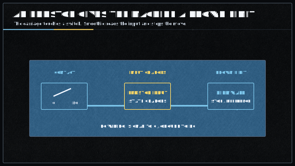
Endstops define the physical limit switches that establish your machine’s home position and travel limits. They can be configured as minimum or maximum position stops, with various electrical configurations (normally open, normally closed, pull-up, pull-down). Proper endstop configuration is critical for safe homing and preventing crashes. For complete documentation, see the Endstops page.
| V1 Setting | V2 Setting | Description |
|---|---|---|
| Always enabled if configured in v2 |
Master enable switch for the traditional root-level endstop configuration method. When set to In v2, endstops are always enabled if configured. |
|
|
Enables CoreXY-specific homing behavior. When enabled, X and Y axes home individually (one at a time) rather than simultaneously, and both motors stop when either endstop is triggered. CRITICAL: Must be enabled for CoreXY and H-Bot kinematics to prevent incorrect homing behavior. |
||
|
Enables linear delta robot homing behavior. When enabled, Applies trim values to correct for endstop position variations. CRITICAL: Must be enabled for linear delta kinematics. |
||
|
Enables rotary delta robot homing behavior. Similar to linear delta, but endstop positions represent actuator angles (in degrees), not cartesian coordinates. CRITICAL: Must be enabled for rotary delta kinematics. |
||
|
Enables SCARA robot arm homing behavior. When enabled, disables the arm solution during homing (homes in actuator space, not cartesian space). Resets arms to plausible minimum angles (-30, 30, 0) before homing to prevent extreme positions. CRITICAL: Must be enabled for SCARA kinematics. |
||
|
Specifies a custom homing order, forcing axes to home one at a time in the specified sequence. Must be 3-6 characters specifying axis letters (XYZABC) in the desired order. IMPORTANT: Any axis not specified in the string will NOT be homed.
|
||
|
Controls whether the Z axis homes before or after the X and Y axes.
Useful for machines with auto bed leveling probes that need Z clearance before XY movement. |
||
|
Controls whether the machine automatically moves to the origin (0,0 or 0,0,0) after homing completes.
|
||
| Not documented in v2 |
If enabled, moves to a predefined park position after homing instead of moving to origin. The park position is set using IMPORTANT: Mutually exclusive with Position is saved to config-override if |
|
|
Number of consecutive reads required to confirm a limit switch trigger — provides debouncing for limit switches (not homing endstops). IMPORTANT: Only used for limit switches (when Higher values provide more filtering but slower response to limit triggers. Default of 100 is suitable for most mechanical switches. |
||
|
Debounce time in milliseconds for homing endstops. When an endstop is triggered during homing, it must remain triggered for this duration before being accepted as a valid trigger. IMPORTANT: Only used for homing endstops during
|
||
|
DELTA/SCARA ONLY. Software trim for the alpha tower/joint endstop, compensating for small variations in endstop positions between towers.
Units are millimeters for linear deltas, degrees for rotary deltas. Set via |
||
|
DELTA/SCARA ONLY. Software trim for the beta tower/joint endstop, compensating for small variations in endstop positions between towers.
Units are millimeters for linear deltas, degrees for rotary deltas. Set via |
||
|
DELTA/SCARA ONLY. Software trim for the gamma tower/joint endstop, compensating for small variations in endstop positions between towers.
Units are millimeters for linear deltas, degrees for rotary deltas. Set via |
||
| Alpha (X axis or alpha tower) minimum limit endstop pin. Set to |
||
| Alpha (X axis or alpha tower) maximum limit endstop pin. Set to |
||
|
In which direction to home.
|
||
|
This gets loaded after homing when NOTE: the homing offset is added to this with |
||
| This gets loaded after homing when |
||
|
This determines how far the X axis can travel looking for the endstop before it gives up. CRITICAL: Set this value larger than your actual machine travel distance to prevent false failures. |
||
| If set to true, the machine will stop if one of the alpha (X axis or alpha tower) endstops are hit during normal operation. Machine halts and enters ALARM state. | ||
| Speed, in millimetres/second, at which to home for the alpha actuator (X axis or alpha tower). This is the first phase of the two-stage homing process. | ||
|
Speed, in millimetres/second, at which to re-home for the alpha actuator (X axis or alpha tower) once the endstop has been hit once — the precision phase of the two-stage homing process. Slower speeds provide more accurate and repeatable homing positions. |
||
| Distance to retract the alpha actuator (X axis or alpha tower) once the endstop is first hit, before re-homing at a slower speed. Must be large enough to fully release the endstop switch. | ||
| Beta (Y axis or beta tower) minimum limit endstop pin. Set to |
||
| Beta (Y axis or beta tower) maximum limit endstop pin. Set to |
||
|
In which direction to home.
|
||
| This gets loaded after homing when |
||
| This gets loaded after homing when |
||
|
This determines how far the Y axis can travel looking for the endstop before it gives up. CRITICAL: Set this value larger than your actual machine travel distance to prevent false failures. |
||
| If set to true, the machine will stop if one of the beta (Y axis or beta tower) endstops are hit during normal operation. Machine halts and enters ALARM state. | ||
| Speed, in millimetres/second, at which to home for the beta actuator (Y axis or beta tower). This is the first phase of the two-stage homing process. | ||
|
Speed, in millimetres/second, at which to re-home for the beta actuator (Y axis or beta tower) once the endstop has been hit once — the precision phase of the two-stage homing process. Slower speeds provide more accurate and repeatable homing positions. |
||
| Distance to retract the beta actuator (Y axis or beta tower) once the endstop is first hit, before re-homing at a slower speed. Must be large enough to fully release the endstop switch. | ||
| Gamma (Z axis or gamma tower) minimum limit endstop pin. Set to |
||
| Gamma (Z axis or gamma tower) maximum limit endstop pin. Set to |
||
|
In which direction to home.
|
||
| This gets loaded after homing when |
||
| This gets loaded after homing when |
||
|
This determines how far the Z axis can travel looking for the endstop before it gives up. CRITICAL: Set this value larger than your actual machine travel distance to prevent false failures. |
||
| If set to true, the machine will stop if one of the gamma (Z axis or gamma tower) endstops are hit during normal operation. Machine halts and enters ALARM state. | ||
|
Speed, in millimetres/second, at which to home for the gamma actuator (Z axis or gamma tower) — the first phase of the two-stage homing process. The Z-axis typically uses a slower rate (4-10 mm/s) for safety, to prevent bed crashes. |
||
|
Speed, in millimetres/second, at which to re-home for the gamma actuator (Z axis or gamma tower) once the endstop has been hit once — the precision phase of the two-stage homing process. The Z-axis often uses the slowest rate (1-5 mm/s) for maximum precision. |
||
|
Distance to retract the gamma actuator (Z axis or gamma tower) once the endstop is first hit, before re-homing at a slower speed. The Z-axis often uses smaller values (1-3 mm) to minimize travel, but the value must still be large enough to fully release the endstop switch. |
Z Probe
The Z Probe module enables bed leveling and probing functionality using various probe types including mechanical switches, proximity sensors, and BLTouch devices. The probe is used to measure bed surface topology for automatic compensation. For complete documentation, see the ZProbe page.
| V1 Setting | V2 Setting | Description |
|---|---|---|
|
Enables the Z-probe module. When set to true, the probe module is loaded and all probing features become available. Set to false to disable probing entirely and free memory if not using a probe. |
||
|
Defines the GPIO pin connected to the probe signal. Use Example: |
||
| Speed at which the probe approaches the bed during actual probing moves, in millimeters per second. Slower speeds improve accuracy but increase total probing time. Typical values: 5-10 mm/s. | ||
| Travel speed between probe points and for initial rapid approach moves, in millimeters per second. Does not affect probing accuracy but reduces total time for multi-point bed leveling operations. Typical values: 50-200 mm/s. | ||
| Speed when retracting from a probe point, in millimeters per second. When set to 0 (default), automatically calculates as slow_feedrate × 2 for faster retraction without sacrificing accuracy. | ||
|
Probe signal debounce time in milliseconds. The probe signal must remain continuously triggered for this duration before being considered a valid trigger. Set to 1 or 2 if your probe is noisy and gives false readings. Higher values reduce false triggers but may affect accuracy. |
||
|
Height above the bed to position the probe before starting each probing move, in millimeters. Once the bed's approximate height is known (after first probe or homing), subsequent probes start from this height. Typical values: 5-10 mm. |
||
|
Maximum distance the probe will travel downward before giving up on a probe attempt, in millimeters — a safety feature to prevent crashes if the probe fails to trigger. If not defined, uses the gamma_max value from endstop configuration. Set to slightly less than your build height. |
||
|
Time to wait before starting each probe move, in seconds. Allows mechanical settling after XY positioning and before the Z probe begins. Particularly useful for piezo Z-probes to avoid false triggers from vibration. Typical values: 0.1-0.5 seconds. |
||
| Probe in +Z direction instead of -Z direction. Used for specialized machine setups where the probe moves upward to find the surface rather than downward. Rarely needed for standard configurations. | ||
|
G-code command(s) to run before each probe point. Used for deployable probes like BLTouch/3DTouch that need to extend or deploy before probing. Multiple commands can be separated by semicolons. Example: |
||
|
G-code command(s) to run after each probe point. Used for deployable probes like BLTouch/3DTouch that need to retract after probing. Multiple commands can be separated by semicolons. Example: |
||
| — |
Enables manual probe attachment mode for removable probes. When enabled, the machine moves to the mount_position and waits for the user to manually attach the probe before probing operations. V2 removed this feature. |
|
| — |
Position in machine coordinates where the machine moves and waits for manual probe attachment when m_attach is enabled. Specified as comma-separated X,Y,Z coordinates. Only used when m_attach is true. V2 removed this feature. |
Leveling Strategies
Leveling strategies define how the firmware compensates for bed irregularities or calibrates delta geometry. Different strategies are optimized for different machine types and use cases.
Three Point Leveling Strategy
Three-point leveling uses measurements at three corners to calculate a plane that represents the bed surface. This is the simplest leveling strategy, suitable for rigid beds with minimal warping. It’s commonly used on delta printers for initial calibration.
| V1 Setting | V2 Setting | Description |
|---|---|---|
|
Enables the three-point leveling strategy, which probes three user-defined points on the bed to calculate a plane equation. The strategy applies Z compensation during printing to keep the nozzle parallel to the bed surface, correcting for bed tilt. This is the simplest leveling strategy and works well for flat beds with simple tilt. In v2, set |
||
|
First probe point coordinates in the machine coordinate system, specified as comma-separated X and Y values. The three points should ideally form an equilateral triangle and be positioned as far apart as possible within the printable area for maximum leveling accuracy. This point becomes the Z=0 reference after the first probe. Format: |
||
|
Second probe point coordinates in the machine coordinate system. Should be positioned to form a triangle with point1 and point3, ideally an equilateral triangle for balanced leveling across the bed surface. The further apart the three points are, the better the leveling accuracy. Format: |
||
|
Third probe point coordinates in the machine coordinate system, completing the triangle with point1 and point2. The three points define the plane used for bed leveling compensation. Maximum leveling accuracy is achieved when the three points form a large equilateral triangle. Format: |
||
|
Offset of the probe tip from the nozzle tip in X, Y, and Z dimensions. These offsets are critical for accurate compensation, as they tell the firmware where the probe is relative to the actual printing nozzle.
Format: |
||
|
Automatically homes the X and Y axes before running the Homing ensures the machine is at a known position before probing begins, which is essential for accurate and repeatable leveling. Disable this only if you want manual control over homing, or are using work coordinate system offsets. Default: |
||
|
Maximum acceptable difference in millimeters between the highest and lowest probe points. If the bed is flatter than this tolerance (the difference between highest and lowest point is less than this value), no compensation plane is applied, as the bed is considered flat enough. Also used to validate the first probe point's repeatability. Default: |
||
|
Enables saving the calculated bed plane to config-override when When enabled, the plane parameters (A, B, C, D coefficients) are saved and can be restored later with Default: |
Delta Calibration Strategy
Delta calibration strategy performs comprehensive calibration of linear delta kinematics including tower positions, delta radius, arm lengths, and Z-height. This strategy is specifically designed for delta printers and uses multiple probe points to optimize geometric parameters.

| V1 Setting | V2 Setting | Description |
|---|---|---|
|
Enables the delta calibration strategy for automatically calibrating linear delta printer geometry. The strategy probes seven points (three at towers, three between towers, one at center) and adjusts endstop trim values and delta radius to minimize height differences. This strategy is specifically for delta kinematics and is automatically loaded for delta printers if no other strategy is specified. In v2, set |
||
|
Radius in millimeters at which to probe the bed for delta calibration. This determines the size of the circular pattern formed by the seven probe points:
The radius should be as large as possible while staying within the printable area. Default: |
||
|
Absolute Z machine position in millimeters to move to after homing and before starting the initial bed probe. This height must be high enough that the probe will not hit the bed during the rapid descent phase — a critical safety parameter that prevents crashes during the first probe approach. Default: |
Delta Grid Calibration
Delta grid calibration creates a detailed height map of the build surface specifically for delta printers, accounting for both mechanical imperfections and bed surface irregularities. This provides more detailed compensation than three-point leveling.

| V1 Setting | V2 Setting | Description |
|---|---|---|
|
Enables the delta grid leveling strategy for height mapping across circular delta printer beds. The strategy probes a grid of points in a circular pattern (skipping corners outside the radius) and stores height offsets. During printing, the firmware interpolates between the nearest four grid points to calculate Z compensation for any XY position. In v2, set |
||
|
Radius of the circular bed area to probe and compensate, in millimeters. The grid probes a square region, but points outside this radius are skipped, creating a circular probe pattern. This radius should be at least as large as the maximum printing radius, to ensure full bed compensation coverage. Default: |
||
|
Grid size in both X and Y dimensions, determining the total number of probe points. A size of 7 creates a 7×7 grid = 49 potential probe points (points outside the radius are automatically skipped). Larger grids give more accurate compensation but increase probing time significantly. Must be an odd number. Default: |
||
|
Offset of the probe tip from the nozzle tip in X, Y, and Z dimensions — compensating for the physical displacement between where the probe triggers and where the nozzle actually is. Correct offsets are essential for accurate bed compensation. Format: |
||
|
Absolute Z machine position in millimeters to move to after homing, before starting the grid probe sequence. This safety parameter prevents the probe from crashing into the bed during the initial descent. Must be high enough to clear the bed surface. Default: |
||
|
Automatically homes all axes before running the Homing ensures the machine is at a known position before probing, which is essential for repeatable and accurate grid generation. Disable only if you want manual control over the homing process. Default: |
||
|
Automatically saves the This allows persistent bed leveling across power cycles without re-probing. Default: |
||
|
Probe tolerance for repeatability checks and validation during grid creation — used to confirm that probe measurements are consistent and repeatable across multiple probes of the same point. Default: |
||
| N/A (feature removed) | DEPRECATED - This setting is no longer supported and will produce an error if used. For square or rectangular beds, use the |
Rectangular Grid Leveling
Rectangular grid leveling creates a detailed height map using probe points arranged in a regular grid pattern. This strategy provides the most accurate compensation for beds with significant warping or irregularities. It’s commonly used on Cartesian and CoreXY printers.
| V1 Setting | V2 Setting | Description |
|---|---|---|
|
Enables the rectangular grid leveling strategy for Cartesian and CoreXY machines. The strategy probes a rectangular area with configurable dimensions and grid density, storing height offsets at each point. During printing, interpolation between the nearest four grid points provides smooth Z compensation across the entire bed. In v2, set |
||
|
Default grid size for both X and Y dimensions if This is a fallback value — specifying Default: |
||
|
Number of probe points in the X dimension, allowing rectangular (non-square) grids. If both Must be an odd number. Default: |
||
|
Number of probe points in the Y dimension, allowing rectangular (non-square) grids. When specified together with Must be odd, to ensure proper interpolation with a center point. Default: |
||
|
Width of the rectangular bed area to probe in the X dimension, measured in millimeters — the total X extent of the probing area. Grid points are evenly distributed across this width. This is a required setting for the rectangular grid strategy to function. |
||
|
Length of the rectangular bed area to probe in the Y dimension, measured in millimeters — the total Y extent of the probing area. Grid points are evenly distributed across this length. This is a required setting for the rectangular grid strategy to function. |
||
|
Offset of the probe tip from the nozzle tip in X, Y, and Z — critical for accurate positioning, since it tells the firmware where the probe actually is relative to the print nozzle. The Z offset is typically Format: |
||
|
Optional absolute Z machine position in millimeters to move to before starting the grid probe. If not set (NAN) or ≤0, probing starts from the current Z position. When set to a valid positive value, it acts as a safety feature, ensuring the probe starts from a known height above the bed. Default: |
||
|
Automatically homes before running Homing ensures the machine starts from a known position, for repeatable and accurate grid generation. Can be disabled for manual homing control. Default: |
||
|
Automatically saves an Enables persistent bed leveling across power cycles without re-probing every time. Default: |
||
|
Probe tolerance in millimeters for repeatability validation during grid creation. Used to verify that probe measurements are consistent and repeatable, ensuring the grid data is reliable before it is used for compensation. Default: |
||
|
Enables two-corners mode, where
This allows dynamic probe area definition but prevents grid saving. Mode can be toggled at runtime with Useful for PCB milling with varying board sizes. Default: |
||
|
Changes the grid display format for When enabled, the output includes X and Y coordinates for each grid point along with the height value, making it easier to understand and visualize the bed topology. Default: |
||
|
Maximum Z height in millimeters where bed compensation is applied. Above this height, no compensation is added to Z moves. Used together with Prevents compensation from affecting tall prints unnecessarily. |
||
|
Z height in millimeters where bed compensation begins to fade out. Between This creates a smooth transition zone where compensation gradually reduces, preventing abrupt changes in Z movement. |
||
|
Enables manual probe attachment mode for removable probes. Before probing begins, the machine moves to This allows use of removable probes that are not permanently mounted on the tool head. Default: |
||
|
Position in machine coordinates where the machine moves and waits for manual probe attachment when Should be a safe, easily accessible position where the operator can comfortably attach the removable probe. Only used if Format: |
||
|
G-code command to execute before each individual probing operation. Use underscore Commonly used to deploy servo-actuated probes like BLTouch (e.g., |
||
|
G-code command to execute after each individual probing operation. Use underscore Commonly used to retract servo-actuated probes like BLTouch (e.g., |
Extruder
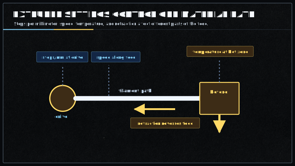
The Extruder module controls filament extrusion for 3D printing, managing the stepper motor that pushes filament through the hotend. It handles acceleration, retraction, and coordinates with temperature control for safe operation. For complete documentation, see the Extruder page.
| V1 Setting | V2 Setting | Description |
|---|---|---|
|
Whether to activate this extruder instance. All configuration for it is ignored if set to Each enabled extruder creates a separate extruder module instance that can be controlled with tool change commands ( Use the |
||
|
Number of stepper motor steps required to move one millimeter of filament through the extruder — a critical calibration value. Depends on your stepper motor steps/revolution (typically 200 for 1.8° motors), microstepping setting (e.g. 16x = 3200 steps/rev), and your extruder gear ratio/hobbed bolt diameter. Calculate as: Fine-tune by extruding a known length and measuring actual extrusion. Can be adjusted at runtime with |
||
|
Filament diameter in millimeters for volumetric extrusion mode. When set to a value greater than
Can be changed at runtime with |
||
|
Maximum acceleration for the extruder stepper motor in Higher values allow faster speed changes but may cause filament grinding or skipped steps if too aggressive; lower values produce smoother extrusion but may cause artifacts during rapid direction changes. Typical values: Affects extruder-only moves (retractions) and the E-axis component of combined moves. Adjust based on your extruder's mechanical capabilities and filament characteristics. Can be changed at runtime with |
||
|
Maximum allowable speed for the extruder stepper motor in Typical values: Too high a value may cause grinding or skipped steps; too low limits print speed. Affects both printing moves and retractions, and can be set per-extruder for multi-extruder setups. |
||
|
Pin for the extruder stepper motor driver's step signal. Each step pulse moves the motor one microstep according to the driver's microstepping configuration, toggling high/low to create the pulse train that drives the motor.
Step frequency equals |
||
|
Pin for the extruder stepper motor driver's direction signal. Controls whether the motor rotates forward (extrude) or backward (retract); the direction pin must be set before step pulses are sent. Typical Smoothieboard pins: Test direction by sending |
||
|
Pin for the extruder stepper motor driver's enable signal. When active, the motor driver is powered and holds position with full torque; when inactive, the driver is disabled and the motor freewheels (no holding torque). Typical Smoothieboard pins: The motor automatically enables before moves and can disable after a timeout (see |
||
|
X-axis offset of this extruder's nozzle from the primary extruder (T0), in millimeters. Used only in multi-extruder setups to compensate for physical nozzle position differences; the firmware automatically applies these offsets when switching tools with Positive values mean this extruder's nozzle is to the right of T0. Measure the offset by homing, moving to a reference point with T0, switching to this tool, and measuring the distance needed to return to the same point. The primary extruder (T0) should always have offsets of |
||
|
Y-axis offset of this extruder's nozzle from the primary extruder (T0), in millimeters. Used only in multi-extruder setups to compensate for physical nozzle position differences. Positive values mean this extruder's nozzle is toward the back (away from Y=0) compared to T0. See Must be accurately calibrated for proper layer alignment when switching between extruders during multi-material or multi-color prints. |
||
|
Z-axis offset of this extruder's nozzle from the primary extruder (T0), in millimeters. Used only in multi-extruder setups to compensate for different nozzle heights — critical for proper first layer when switching extruders. Positive values mean this extruder's nozzle is higher (further from the bed) than T0. Calibrate by homing Z, moving to a known position with T0, switching to this tool, and measuring the height difference. Even small differences (0.05mm) can cause first layer problems. Some slicers can compensate for Z-offset in G-code, but it's best to configure it in firmware for consistent behavior across all print jobs. |
||
|
Amount of filament to retract during firmware retraction, in millimeters. Used by
Too little retraction causes stringing; too much can cause clogs or air gaps. The total retract amount includes this length plus |
||
|
Speed at which filament is retracted during firmware retraction, in
Faster retractions reduce stringing but may cause grinding or skipped steps if too fast. Direct drive can typically handle faster retractions than Bowden. Speed should be fast enough to quickly relieve pressure but not so fast that it damages filament or causes extruder jamming. Can be changed at runtime with |
||
|
Additional length of filament to extrude when recovering (unretract) beyond the retracted amount. Used by
Compensates for material properties, oozing during travel, or pressure changes in the melt zone. Fine-tune to eliminate blobs (reduce value) or gaps (increase value) after travel moves. Can be changed at runtime with |
||
|
Speed at which filament is recovered (unretracted) during firmware unretraction, in
Slower recovery speeds help prevent blobs and allow time for pressure in the nozzle to build back up smoothly. Too fast can cause blobs; too slow can cause gaps at the start of extrusion. Should generally be less than |
||
|
Amount to lift the Z-axis during retraction, in millimeters (Z-hop / Z-lift feature). When
Z-hop reduces the chance of the nozzle dragging through or knocking over printed parts during travel moves — especially useful for tall thin features, parts with significant Z-variation, or materials prone to warping. Trade-off: increases print time due to extra Z movements. Can be changed at runtime with |
||
|
Speed for Z-axis movement during Z-lift operations, in
Faster Z-lift reduces travel time overhead but may cause ringing or mechanical stress on Z-axis components. Should not exceed the Z-axis maximum speed. Can be changed at runtime with |
Temperature Control
The Temperature Control module manages heating and cooling for components like hotends, heated beds, and heated chambers. It supports multiple temperature sensors (thermistor, thermocouple, PT100), PID control for precise temperature regulation, and comprehensive safety features including thermal runaway protection. For complete documentation, see the Temperature Control page.
| V1 Setting | V2 Setting | Description |
|---|---|---|
|
Whether to activate this temperaturecontrol module. You can create as many temperaturecontrol modules as you want, simply by giving a new module a name and setting its |
||
| Pin for the thermistor to read. ADC ports TH1 to TH4 are pins |
||
|
Pin that controls the heater. This can be used to control a Mosfet on board or an external Solid State Relay. Set to |
||
|
Set the type of sensor used to read temperature.
|
||
| Set the thermistor model for this module. Several different common models are pre-defined, see thermistor choice guide. | ||
| Manually set the |
||
|
Manually set the |
||
| Reference temperature in degrees Celsius for the thermistor resistance |
||
|
Series resistor value in ohms in the thermistor circuit. This is a board property and usually doesn't need to be changed. Standard Smoothieboard uses 0 (no series resistor). |
||
|
Pull-up resistor value in ohms in the thermistor circuit. This is a board property and usually doesn't need to be changed. Standard Smoothieboard uses 4700 ohms. |
||
|
Steinhart-Hart equation coefficients (c1, c2, c3) for accurate temperature calculation across the full temperature range. Specify as three comma-separated floats (no spaces). This enables the most accurate temperature measurement method. |
||
|
Three temperature/resistance pairs used to auto-calculate Steinhart-Hart coefficients. Format: Best practice: use the 25°C, 150°C, and 240°C points from the thermistor datasheet. |
||
| Forces use of beta-based predefined thermistor table instead of Steinhart-Hart coefficients when using a predefined thermistor name. This setting only applies when a predefined thermistor name is specified. | ||
| If the sensor is set to |
||
| If the sensor is set to |
||
| V1 only | Required ADC pin for reading AD8495 thermocouple amplifier output. Only used when sensor type is |
|
| V1 only |
Temperature offset in degrees Celsius for AD8495 sensor calibration. Only used when sensor type is
|
|
| V1 only | Required ADC pin for reading PT1000 RTD sensor. Only used when sensor type is |
|
|
How many times per second to read temperature from the sensor. This setting determines how often the sensor is read and PID calculation is performed. Higher values improve control stability but increase CPU load. |
||
| V1 only | How many times per second to switch the heating element on or off. Set to a low value (20) if using a Solid State Relay. | |
|
Maximum PWM value for the heating element. This can be from
|
||
| Set to true to use bang bang control rather than PID. Bang-bang (on/off) control is suitable for slow-response systems like heated beds with mechanical relays or SSRs. | ||
| Set to the temperature in degrees C to use as hysteresis for bang bang control. Creates a deadband of ±hysteresis around the target temperature to prevent rapid heater switching. | ||
|
P factor for PID temperature regulation. Determines the controller's response to current temperature error. Higher values increase responsiveness but may cause oscillation. Use |
||
|
I factor for PID temperature regulation. Eliminates steady-state temperature error over time by accumulating past errors. Internally scaled by PIDdt (1/readings_per_second). Higher values eliminate offset faster but risk overshoot. Use |
||
|
D factor for PID temperature regulation. Reduces overshoot by damping the rate of temperature change. Internally scaled by PIDdt. Higher values reduce overshoot but may slow response. Use |
||
|
Maximum value for the I variable in the PID control. This should usually be set to about the same value as If you get a strong (>10°C) overshoot on startup, try setting this to a value lower than |
||
|
Enable alternative integral windup protection behavior.
|
||
| V2 only |
Use Proportional on Measurement instead of Proportional on Error. PonM mode reduces overshoot when changing setpoint by applying the P term to measurement changes rather than error changes. See this article for a detailed explanation. |
|
| Calling this M-code will return the current temperature. Standard: |
||
|
This is the M-code for simply setting the temperature. For example here, the value is Standard: |
||
|
This is the M-code for setting the temperature then waiting for that temperature to be reached before doing anything. For example here, the value is Standard: |
||
| The letter this module's temperature will be identified as in the |
||
| V2 only |
Tool number for M-code addressing and tool selection. Determines which temperature controller is addressed by T commands and whether the controller responds to tool change commands.
|
|
| If set, no temperature above this will be accepted and if the temperature exceeds this value the system will be forced into a HALT state. This protects against thermal runaway and prevents damage to the machine and surroundings. | ||
|
Minimum safe temperature threshold. If the sensor reads below this value (e.g., thermistor disconnected), the system immediately enters HALT state and the heater turns off. This is a critical safety feature that detects sensor failures. |
||
|
If we take longer than this many seconds to heat up, the system will be forced into a HALT state. Set to 0 to disable. Default is 900 seconds. Detects heater failure, insufficient power, or a disconnected heater. |
||
|
If we take longer than this many seconds to cool down, the system will be forced into a HALT state. Set to 0 to disable. Default is disabled. Detects a stuck heater or sensor failures. |
||
|
If set to non-zero, and the target temperature is reached, and temperature diverges from the target temperature by more than this, the system will be forced into a HALT state. Detects a heater stuck on, sensor failure, cooling system failure, or a part cooling fan blowing on the thermistor. |
||
|
Acceptable temperature tolerance (±°C) for determining when the target temperature has been "reached". Temperature must be within (target ± runaway_error_range) to be considered at target and to satisfy Default is ±1.0°C. |
||
| V1 only | Temperature preset 1 for quick selection (e.g., 200°C for PLA hotend temperature). | |
| V1 only | Temperature preset 2 for quick selection (e.g., 230°C for ABS hotend temperature). |
Temperature Switch
The Temperature Switch module automatically controls outputs (fans, coolers, heaters) based on temperature thresholds. This is commonly used for hotend cooling fans that turn on when the hotend reaches a certain temperature, or chamber heaters that maintain ambient temperature. For complete documentation, see the Temperature Switch page.
| V1 Setting | V2 Setting | Description |
|---|---|---|
|
Creates and enables a new TemperatureSwitch module instance. When set to true, this module monitors temperature from a specified TemperatureControl module and automatically controls a Switch module based on configured thresholds and trigger conditions. Multiple temperature switch instances can be configured simultaneously by using different instance names — each instance requires a unique module name (e.g., hotend, bed, chamber). The module will not function unless enabled, and must be accompanied by valid designator and switch configuration. |
||
|
Specifies which TemperatureControl module to monitor by matching its designator character. The temperature switch reads the current temperature from the temperature control module with this designator and uses it to determine when to trigger the switch. If multiple temperature control modules share the same designator, the highest temperature among them is used for comparison. Matching is case-sensitive —
The temperature reading is polled at intervals defined by the heatup_poll and cooldown_poll settings. |
||
|
Specifies the name of the Switch module to be controlled by this temperature switch. When temperature conditions are met, this switch is toggled on or off according to the configured trigger mode and inversion settings. The switch must be configured and enabled in the switch module settings before it can be controlled — the specified switch must exist and be properly configured with output_pin and output_type. It typically controls one of the small MOSFETs on the Smoothieboard. Switch state is only changed when armed (either always armed if arm_mcode=0, or manually armed via M-code). |
||
|
Legacy parameter name for specifying the switch module to control. Functionally identical to the This parameter has been replaced by |
||
|
Sets the temperature threshold in degrees Celsius at which the switch state changes. The exact behavior depends on the trigger mode:
Temperature comparison uses For typical hotend cooling applications, set this 10-20°C below the hotend operating temperature. Inverted mode reverses the on/off logic but uses the same threshold comparison — the threshold applies regardless of whether the switch is inverted or not, since inversion only affects the final switch output state. |
||
|
Defines the polling interval in seconds when the system is in the LOW_TEMP state (current temperature < threshold_temp) — i.e. while heating up. A shorter interval gives faster response when temperature rises toward the threshold, but increases system overhead. The initial state uses the heatup_poll interval and performs its first check immediately. Once temperature crosses the threshold, polling automatically switches to the cooldown_poll interval. Polling occurs on the second tick event, so actual timing may vary by ±1 second.
|
||
|
Defines the polling interval in seconds when the system is in the HIGH_TEMP state (current temperature >= threshold_temp) — at or above operating temperature, or cooling down. A longer interval reduces system overhead during stable high-temperature operation, while still monitoring for temperature drops that should trigger switch state changes. Slower polling during stable operation reduces system load, and is suitable for applications where the switch should remain on for extended periods. Once temperature falls below the threshold, polling automatically switches to the heatup_poll interval. Polling occurs on the second tick event, so actual timing may vary by ±1 second. Higher values reduce processing overhead when temperature is stable above threshold. |
||
|
Determines the triggering behavior mode of the temperature switch — whether it responds to sustained temperature levels, rising temperature edges, or falling temperature edges. The mode fundamentally changes how temperature threshold crossings are interpreted, and affects the arming behavior.
Edge-triggered modes (rising/falling) automatically disarm after triggering, requiring re-arming for subsequent triggers. Invalid trigger values default to "level" mode. State changes only occur when temperature crosses the threshold boundary, not during stable states. Works in conjunction with the inverted setting — inversion is applied after trigger logic determines switch state. |
||
|
Reverses the normal switch control logic. When enabled, the switch turns off when temperature exceeds the threshold (instead of turning on), and turns on when temperature falls below the threshold. This is useful for heaters or devices that should activate during cooling rather than heating.
The inversion occurs at the final switch control stage, applied in the Useful for controlling heating elements that should turn off when target temperature is reached. Common use case: emergency cooling systems that activate when temperature drops too low. |
||
|
Defines a custom M-code command that must be executed to arm the temperature switch before it can trigger. This provides manual control over when the temperature switch is active, preventing unwanted switch activation. It also acts as a safety mechanism for critical temperature-dependent operations — disarmed switches do not control their associated switch modules.
|
Tools
Laser
The Laser module provides PWM control for laser cutters and engravers, with power modulation based on feed rate and optional fire button support. It includes safety features and supports both continuous and pulsed operation modes. For complete documentation, see the Laser page.
| V1 Setting | V2 Setting | Description |
|---|---|---|
|
Whether to activate the laser module at all. The laser module is used for laser cutting using a laser diode or CO2 laser tube. When set to Must be enabled before any other laser settings take effect. |
||
|
This pin controls the laser. Pulse width is modulated (PWM) to vary power output — PWM duty cycle directly controls laser power output percentage. This is the preferred and more descriptive parameter for specifying the PWM control pin for the laser. CRITICAL: Only hardware PWM pins are supported:
Using non-PWM pins will disable the laser module with an error message. Inverting pin logic with the |
||
|
DEPRECATED: Legacy parameter that specifies the pin controlling the laser through PWM. Superseded by If this pin is not connected, the system will check Use |
||
|
This pin turns on when the laser turns on, and off when the laser turns off — a simple on/off signal synchronized with laser firing, independent of the PWM power level. This is a digital on/off signal, NOT PWM: it is either high or low. Commonly used to:
|
||
|
The maximum duty cycle that will be applied to the laser, as a value from Example: setting WARNING: Does not provide emergency shutoff — use a kill switch for safety. |
||
|
Sets the minimum PWM duty cycle (baseline power) for the laser, as a value from Useful for some diode setups: keeps laser diodes thermally stable by preventing complete shutoff and reduces thermal stress from constant on/off cycling. During cutting operations, actual power is scaled between this minimum and the maximum power setting. WARNING: Non-zero values mean the laser is always slightly active when the module is enabled. |
||
|
DEPRECATED: Replaced by If you have old configuration files using this parameter, it will still work, since it provides the fallback default value for |
||
|
Maximum S-value accepted from G-code commands. Determines the S-value range:
The S-value is scaled to the 0-1 range internally based on this maximum. Does not affect actual laser power output, only G-code interpretation — this allows using G-code from different CAM packages without modification. Example: with |
||
|
Whether laser power should be proportional to the current speed: as movement speed ramps up (and down), laser power is proportionally adjusted so that the amount of laser power/quantity of photons for a given distance/area stays constant, even as speed increases or decreases progressively. This is true by default. Enables automatic power scaling based on actual instantaneous movement speed. When enabled (default): This:
Can also be controlled at runtime via |
||
|
PWM frequency expressed as the period in microseconds — sets the PWM period (and thus frequency) for laser control. The PWM frequency equals 1,000,000 divided by this period value. This frequency affects how smoothly laser power can be controlled and must be appropriate for your specific laser driver electronics; the system uses this period to limit the maximum rate of power adjustments. Default is |
||
|
Default S value for laser operations when no S parameter is specified in G-code, as a fraction from Typical laser default is |
Spindle
The Spindle module controls spindle motors for CNC milling and routing operations. It supports both PWM speed control and relay-based on/off control, with configurable speed ranges and direction control. For complete documentation, see the Spindle page.
| V1 Setting | V2 Setting | Description |
|---|---|---|
|
Enables the spindle control module. When true, the spindle module is loaded and available for G-code control (M3/M5 commands).
|
||
|
Spindle control mode. V1 supports three types:
V2 only supports:
|
||
|
PWM output pin for spindle control. Must be hardware PWM-capable on Smoothieboard: Controls spindle speed either directly (for PWM-capable spindles) or through a VFD's analog input. Pin can be inverted with the ! suffix (e.g., 2.4!). |
||
|
PWM frequency for spindle control.
Most VFDs and spindle controllers work with 1-50 kHz — check your VFD documentation for the required frequency. |
||
|
Maximum PWM duty cycle (0.0-1.0). Acts as both a safety limit and a calibration factor. Some spindle controllers (like MC2100) require less than 100% duty cycle for maximum speed — MC2100 uses 0.85. Setting below 1.0 limits maximum spindle speed even when G-code requests full power, protecting the motor from overcurrent. |
||
|
Controls spindle behavior during an emergency stop.
This is a safety-critical setting — use with extreme caution. |
||
| — |
Tachometer input pin for closed-loop RPM control (V1 PWM mode only). Must be an interrupt-capable pin on Port 0 or Port 2 (pin number must be 2.x or 0.x). Receives pulses from a hall-effect sensor, optical encoder, or other tachometer, and is used with the PID controller for precise RPM maintenance. Not available in V2. |
|
| — |
Number of tachometer pulses per spindle revolution (V1 PWM mode only). Used to calculate actual RPM from tachometer feedback.
Essential for accurate RPM calculation in closed-loop mode. Not available in V2. |
|
| — |
Default RPM when M3 is issued without an S parameter (V1 PWM mode only) — if G-code contains "M3" without specifying speed, this RPM is used. Default: 5000 RPM. Only applies to the PWM spindle type with feedback control. Not available in V2. |
|
| — |
PID proportional term for closed-loop spindle control (V1 PWM mode only). Controls how aggressively the controller responds to RPM error. Higher values give faster response but may cause oscillation; lower values give smoother operation but slower response. Requires tuning for the specific spindle.
Not available in V2. |
|
| — |
PID integral term for closed-loop spindle control (V1 PWM mode only). Eliminates steady-state error by accumulating error over time. Higher values eliminate offset faster but may cause overshoot; set too high and the system becomes unstable. Requires tuning for the specific spindle.
Not available in V2. |
|
| — |
PID derivative term for closed-loop spindle control (V1 PWM mode only). Responds to the rate of change of error, providing damping to reduce overshoot and oscillation. Higher values give more damping but may slow response and amplify noise. Often set lower than the P and I terms.
Not available in V2. |
|
| — |
Low-pass filter time constant in seconds for tachometer smoothing (V1 PWM mode only). Filters out noise and transient fluctuations in RPM measurement. Higher values give more smoothing but slower response to actual speed changes; lower values give faster response but may amplify tachometer noise. Default: 0.1 seconds. Not available in V2. |
|
| — |
Minimum RPM when the spindle is on (V1 analog mode only). When the spindle is enabled, speed cannot go below this value — it prevents stalling and ensures a minimum cutting speed. If G-code requests a speed below min_rpm (but greater than 0), this minimum is used instead. Default: 100 RPM. Not available in V2. |
|
| — |
Maximum RPM at 100% PWM (V1 analog mode only). Calibrates the PWM output to the spindle's maximum speed. For example, if your VFD is configured for 24000 RPM maximum and you request 12000 RPM (S12000), the system outputs 50% PWM. Essential for accurate speed control with VFDs and ESCs. Default: 5000 RPM. Not available in V2. |
|
| — |
Optional digital output pin to enable a VFD/power supply (V1 analog mode only). Typically connected to the VFD's RUN/ENABLE input via an optocoupler. Goes high when the spindle is commanded on ( Not available in V2 (use a separate switch instance instead). |
|
| — |
VFD manufacturer/model for Modbus control (V1 modbus mode only). Currently only supports "huanyang" VFDs, and determines the Modbus protocol and register mapping used for RS485 communication. Huanyang VFDs must be configured for RS485 control before use:
Not available in V2. |
|
| — |
RS485 receive pin for Modbus communication (V1 modbus mode only). Used with the TX and DIR pins to communicate with Modbus VFDs. Requires an RS485 transceiver chip (MAX485 or similar) between Smoothieboard and VFD. This pin receives data from the VFD. Not available in V2. |
|
| — |
RS485 transmit pin for Modbus communication (V1 modbus mode only). Used with the RX and DIR pins to communicate with Modbus VFDs. Requires an RS485 transceiver chip. This pin sends data to the VFD. Not available in V2. |
|
| — |
RS485 direction control pin (V1 modbus mode only). RS485 is half-duplex, so a single pair of wires is used for both sending and receiving. This pin switches the RS485 transceiver between transmit and receive modes — typically connected to the DE/RE pins on a MAX485 chip. Not available in V2. |
|
| — |
G-code command to turn the spindle on (V2 only, via the switch module). Typically M3 for spindle clockwise, but can be configured to any G-code or M-code. Not needed in V1 (M3 is hardcoded). |
|
| — |
G-code command to turn the spindle off (V2 only, via the switch module). Typically M5 for spindle stop, but can be configured to any G-code or M-code. Not needed in V1 (M5 is hardcoded). |
Input Controls
Switch
The Switch module provides general-purpose digital I/O control, allowing you to define custom switches and buttons that trigger actions, control outputs, or execute G-code sequences. Switches can be momentary or toggle, with configurable input and output pins. For complete documentation, see the Switch page.
| V1 Setting | V2 Setting | Description |
|---|---|---|
|
Creates and enables a new Switch module instance — when set to true, the switch is active and responds to configured inputs and controls outputs. Set to false to disable the switch instance without removing its configuration. Each switch instance requires a unique name. |
||
|
Specifies a GPIO pin that controls the switch state through hardware input. When the pin becomes high the switch changes to ON, and when it becomes low it changes to OFF (exact behavior depends on input_pin_behavior). Input pins are polled at 100ms intervals. The pin can be configured with pullup (^) or inverted (!) modifiers. |
||
|
Defines how the input pin controls the switch state.
|
||
|
Specifies a G-code or M-code command that sets the switch to the ON state — when this command is received, the switch turns ON. Supports optional subcode matching via switch.{name}.subcode. The S parameter can control the PWM value for PWM-type outputs. Commands are queued and executed synchronously with motion. |
||
|
Specifies a G-code or M-code command that sets the switch to the OFF state — when this command is received, the switch turns OFF. Supports optional subcode matching via switch.{name}.subcode. Commands are queued and executed synchronously with motion. |
||
|
Specifies a subcode for input command matching, allowing multiple switch instances to respond to different subcodes of the same base command (e.g., M106.1 vs M106.2). Subcode 0 is the default and matches commands without explicit subcodes. Only evaluated when input_on_command and/or input_off_command are set. |
||
|
Specifies the GPIO pin controlled by the switch — set low when the switch is OFF, and high when it is ON. The pin's exact behavior depends on output_type (digital on/off, PWM, hardware PWM, or software PWM). For hardware PWM (hwpwm), the pin must be PWM-capable. |
||
|
Sets the type of output for the switch output pin.
|
||
|
Specifies a G-code command to execute when the switch transitions to the ON state. The command is sent to the G-code parser and executed. Underscores in the command are replaced with spaces to allow multi-word commands (e.g., M117_Hello_World becomes M117 Hello World). Commands execute in the main loop when the switch state changes to ON. |
||
|
Specifies a G-code command to execute when the switch transitions to the OFF state. The command is sent to the G-code parser and executed, with underscores replaced by spaces before execution. Commands execute in the main loop when the switch state changes to OFF. Special handling: $J STOP triggers an emergency stop request for continuous jog (only works with input pins). |
||
|
Sets the initial state of the switch when the system boots.
For PWM outputs with startup_state true, default_on_value is used instead of startup_value. For input-pin switches (momentary mode), the initial state is read from the pin and overrides this setting. |
||
|
Sets the PWM value when the switch is OFF, or at startup if startup_state is false.
Also used as the PWM value on HALT for HWPWM and SWPWM. startup_state must be false for this to take effect. |
||
|
Sets the PWM duty cycle percentage when the switch is turned ON without an explicit S parameter. Only applies to hardware PWM (hwpwm) and software PWM (swpwm) output types. Value range is 0-100 (percentage). Used when the switch is turned on via command, or when startup_state is true. Can be overridden by an S parameter in commands (e.g., M106 S75 sets to 75%). |
||
|
Sets the maximum PWM value for sigma-delta PWM output, allowing the maximum output power/speed to be limited when using PWM mode. The S parameter in commands is scaled from 0-255 to 0-max_pwm. Only applies to the SIGMADELTA (pwm) output type, not hwpwm or swpwm. Default is 255, meaning no limiting (full range). |
||
|
Sets the PWM period in milliseconds for hardware PWM and software PWM outputs — this determines the PWM frequency. Only applies to HWPWM and SWPWM output types. A lower period means higher frequency and faster PWM switching.
|
||
|
Defines the pin state (0 or 1) to set during a crash, watchdog reset, or debug halt condition — a safety feature ensuring outputs are in a safe state when the system fails. Different from halt_set_to, which handles |
||
|
Defines the switch state (true or false) to set during a HALT condition (typically triggered by For digital outputs, this boolean directly controls the pin state (high/low). For PWM outputs (hwpwm/swpwm), startup_value is used as the actual value instead. Different from failsafe_set_to, which handles crash/debug conditions. |
||
|
When set to true, prevents the switch from changing state during HALT conditions ( Automatically set to true for input-pin switches and cannot be overridden. Useful for non-safety-critical outputs (lights, status indicators) that should maintain their state during emergency stops. |
Joystick
The Joystick module enables manual machine control using analog joystick inputs, allowing operators to jog axes smoothly without G-code commands. This is useful for manual positioning, tool changes, and setup operations.
| V1 Setting | V2 Setting | Description |
|---|---|---|
| Not available in v2 |
If true, creates and enables a new Joystick module with the specified name. The joystick module reads analog input from joystick devices and uses it to control machine movement via the Jogger module or other control systems. Each joystick instance requires a unique name. |
|
| Not available in v2 |
Specifies which SmoothieBoard pin should be used to read the analog joystick value. The pin must be one of the analog-capable pins (typically Connect the joystick wiper (output) to this pin, with the potentiometer ends connected to 3.3V and ground. |
|
| Not available in v2 |
Sets how many times per second to update the joystick reading. Higher values give more responsive control but use more CPU time.
|
|
| Not available in v2 |
Sets what voltage will map to zero output — typically the center position of the joystick, usually around 1.65V (half of 3.3V). The joystick module subtracts this offset from the measured voltage before scaling. It can also be determined automatically using the auto_zero feature. |
|
| Not available in v2 |
Sets what voltage will map to +1 or -1 output, defining the full range of motion for the joystick.
Typical value is 3.3V (or close to it, like 3.2V) for maximum range. |
|
| Not available in v2 |
If true, enables the auto-zeroing feature, which automatically determines the zero_offset value at startup by averaging readings during the startup_time period. This is useful for joysticks where the center position voltage may vary slightly between devices. Do not move the joystick during startup when this is enabled. |
|
| Not available in v2 |
Sets how long (in milliseconds) after SmoothieBoard resets to obtain readings to average for the auto-zero offset calculation. Must be at least 1000 / refresh_rate to ensure sufficient samples, but should not be too long, to avoid the joystick being moved during measurement. Typical value is 1000ms (1 second). |
|
| Not available in v2 |
Sets the default value of the joystick output during the startup_time period when auto-zeroing is active. This value should be between -1 and 1, and is typically 0 to indicate no movement during calibration — preventing unwanted motion while the auto-zero feature is determining the center position. |
Jogger
The Jogger module provides simple manual jog controls using buttons or encoders, with configurable step sizes and speeds. Unlike the joystick module which uses analog inputs, jogger uses discrete digital inputs for precise incremental movements.
| V1 Setting | V2 Setting | Description |
|---|---|---|
| Not available in v2 | If true, enable the Jogger module. The Jogger module allows you to control machine movement using joystick input, providing smooth continuous motion in the direction of the joystick rather than discrete steps. | |
| Not available in v2 |
Specifies the module name of the Joystick module that the alpha (first) jog axis will read from — connecting a joystick instance to the first axis of jogging control. The value should be the name of a configured joystick module (e.g., "horizontal", "vertical"). |
|
| Not available in v2 |
Specifies the module name of the Joystick module that the beta (second) jog axis will read from — connecting a joystick instance to the second axis of jogging control. The value should be the name of a configured joystick module (e.g., "horizontal", "vertical"). |
|
| Not available in v2 |
Sets a comma-separated list of machine axes which will be controlled by the jogger. Axis letters are given in order of jog axis alpha, beta, etc. The first item in the list is used on startup. Issuing the toggle axes command (M778 by default) cycles between the items in the list.
Example: "XY,XZ,-Z" allows toggling between XY control, XZ control, and no alpha axis with Z beta axis. |
|
| Not available in v2 |
Sets which M-code number the "set axes" command will use. For example, if set to 777, use M777 to set the jog axes. This command allows you to directly specify which axes to control with the joystick (e.g., M777 XY sets jogging to control X and Y axes). |
|
| Not available in v2 |
Sets which M-code number the "toggle axes" command will use. For example, if set to 778, use M778 to toggle the jog axes. This command cycles through the axis combinations specified in the jog_axes setting, allowing you to switch between different control modes (e.g., XY mode, XZ mode, etc.). |
|
| Not available in v2 |
Sets the maximum speed the machine will jog, in mm/min — the speed reached when the joystick is pushed to its maximum extent. If not specified, the Jogger uses the general configuration "default_seek_rate" ( Lower values provide finer control; higher values allow faster positioning. |
|
| Not available in v2 |
Sets the threshold the joystick must cross before movement occurs — a value between 0 and 1 representing the fraction of joystick movement required to start jogging. For example, 0.05 means the joystick must be moved 5% from center before motion begins. This prevents unwanted motion from small joystick movements or electrical noise. Increase this value if you experience drift or unwanted motion. |
|
| Not available in v2 |
Sets the non-linearity of the joystick-to-speed conversion function. Values greater than 1.0 create a curved response where small joystick movements result in proportionally slower speeds, giving finer control near center. A value of 1.0 is linear (50% joystick movement = 50% max speed).
Higher values provide more precise control for small adjustments but require larger movements to reach full speed. |
|
| Not available in v2 |
Specifies how many times per second to read the joysticks and update the jog motion. Higher values provide smoother, more responsive control but use more CPU time. Typical value is 100 Hz. Must be coordinated with the joystick module's refresh_rate setting. |
|
| Not available in v2 |
Sets the number of tiny movement segments per second while jogging. The jogger breaks continuous motion into small discrete segments for smooth execution; higher values create smoother motion but require more processing. Typical value is 10 Hz. This is different from refresh_rate: refresh_rate determines how often joystick position is read, while segment_frequency determines how often new movement commands are generated. |
Panel & Display
The Panel module handles communication with LCD displays and control panels, supporting various display types including RepRap Discount Full Graphic Smart Controller, Viki2, and other common 3D printer displays. Panels provide local control without requiring a host computer. For complete documentation, see the Panel page.
| V1 Setting | V2 Setting | Description |
|---|---|---|
|
Enables the panel interface module. Panels provide a screen, an encoder wheel and/or a set of buttons, used to control your machine without requiring a computer connection. When enabled, the panel module initializes the LCD driver, configures input devices, and registers for system events to display machine status and accept user input. If disabled, the panel module is completely removed from memory. |
||
|
Specifies the type of panel connected to the Smoothieboard. Each panel has specific interface and driver requirements, so the correct panel type must be set. The value determines which panel driver is loaded and initialized. Different panels have different pin requirements, button configurations, and display capabilities. |
||
|
Selects which SPI channel to use for panel communication. The Smoothieboard has two SPI channels with different pin assignments. Channel selection affects which physical pins are used for MOSI, MISO, and SCLK signals. Most panels use channel 0 by default. |
||
|
Specifies the CS (Chip Select) pin used to select the panel device on the SPI bus. CS allows multiple devices to share the same SPI port by activating only the selected device. When CS is low (active), the panel responds to SPI commands; when high (inactive), the panel ignores SPI traffic. |
||
|
|
||
|
|
||
|
|
||
|
Number of lines to offset the menu lines by on screen. On some panels, this value must be set to Adjust if menu items don't align properly on your display. |
||
|
A pin for the encoder wheel. Encoders have two pins, A and B; set this to The |
||
|
B pin for the encoder wheel. Encoders have two pins, A and B; set this to The |
||
|
|
||
|
Pin for the click ("enter" or "select") button, typically pressed to select menu items, confirm actions, and accept value changes. The |
||
|
Pin for the back ("escape" or "cancel") button, which returns to the previous menu level or cancels the current operation. On Viki2 panels, this pin may be used for either back button or pause button functionality. |
||
|
|
||
|
|
||
|
|
||
|
|
||
|
Pin for the buzzer, which provides audio feedback for button presses and alerts. Some panels have a built-in buzzer that requires this pin to be configured. |
||
|
Pin for the red LED on Viki2 panels, which typically indicates heating status or errors. Only available on Viki2 and similar panels with status LEDs. |
||
|
Pin for the blue LED on Viki2 panels, which typically indicates cooling or idle status. Only available on Viki2 and similar panels with status LEDs. |
||
|
If using a Viki or SSD1306, this pin drives the C/D (Command/Data) pin on the display. It distinguishes between command and data bytes in the SPI communication. |
||
|
If using an SSD1306, this pin is sometimes required and connects to the reset pin on the display. The reset pin is used to initialize the display controller. |
||
|
If using the The universal adapter uses this pin for daisy-chaining multiple devices. |
||
|
X (Alpha) axis jogging feedrate in millimeters/minute, used when jogging from the panel screen. Adjust based on your machine's capabilities and desired jogging speed. |
||
|
Y (Beta) axis jogging feedrate in millimeters/minute, used when jogging from the panel screen. Adjust based on your machine's capabilities and desired jogging speed. |
||
|
Z (Gamma) axis jogging feedrate in millimeters/minute, used when jogging from the panel screen. Typically slower than XY jogging, for precision and safety. |
||
|
Temperature to set the hotend to when using the pre-heating menu item on the panel — a quick-access, one-button preset for heating to a commonly used temperature. Set this to match your most commonly used filament type. |
||
|
Temperature to set the bed to when using the pre-heating menu item on the panel — a quick-access, one-button preset for heating to a commonly used temperature. Set this to match your most commonly used filament type. |
||
|
Set to Enables an additional SD card interface beyond the onboard SD slot. |
||
|
Set the SPI channel the external SD card is on. This must match the SPI channel used by the panel if they share the same SPI port, or can be a different channel if separate. |
||
|
Set the CS (Chip Select) pin for the external SD card. This allows multiple devices to share the same SPI port, as long as each has a unique CS pin. |
||
|
SD card detect signal pin, which detects when an SD card is inserted or removed. Set to |
||
|
|
||
|
When set to You can create any number of custom entries, as long as each has a different name. |
||
|
The name displayed in the panel's menus — what the user sees when browsing the menu. Underscores ( |
||
|
The command executed when the menu entry is selected and clicked. The |
Network
The Network module enables Ethernet connectivity on supported boards, allowing remote control, file upload, and web interface access. Network functionality requires appropriate hardware support. For complete documentation, see the Network page.
| V1 Setting | V2 Setting | Description |
|---|---|---|
|
Master enable switch for the entire Ethernet network functionality. When disabled, the network module is completely unloaded to free system resources (approximately 8KB RAM). Must be set to |
||
|
If set to The service itself does not provide authentication or encryption. Restrict it to a trusted network. |
||
|
If set to The protocol is unencrypted and has no authentication. Use it only on a trusted network. |
||
|
If set to Provides direct filesystem access similar to NFS or SMB. |
||
|
Configures the IP address assignment method for the Smoothieboard. Set to When using a static IP, you must also configure |
||
|
Defines the subnet mask for static IP configuration — the netmask determines which portion of the IP address identifies the network and which portion identifies the host. Only used when With DHCP, this setting is ignored and the subnet mask is provided automatically by the DHCP server. |
||
|
Specifies the default gateway (router) IP address for static IP configuration — used for routing traffic outside the local network. Only used when With DHCP, the gateway is provided automatically by the DHCP server. |
||
|
Allows manual override of the Ethernet MAC (Media Access Control) address. By default, Smoothieboard auto-generates a unique MAC address based on the CPU's serial number, using a cryptographic hash. Only set this if you experience MAC address conflicts on your network, or need to preserve a specific MAC address after hardware replacement. |
||
|
Sets a hostname that is sent to the DHCP server during IP address requests. Some DHCP servers register this hostname in local DNS, letting you access the Smoothieboard by name (e.g., Only used when |
||
|
Uses the DHCP-provided DNS server when set to DNS is required when |
||
|
Enables the Smoothieware V2 FTP server on TCP port 21. This is unencrypted standard FTP. It is neither SFTP nor the V1 Simple File Transfer Protocol service on port 115. |
||
|
Requests the time from an NTP server when the V2 network starts and writes it to the real-time clock. The network and DNS configuration must work before hostname-based NTP servers can resolve. |
||
|
Sets the hostname of the NTP server used by Smoothieware V2. |
||
|
Applies a fixed integer offset in hours to the NTP result before setting the V2 real-time clock. It does not implement daylight-saving rules or fractional-hour time zones. Use zero to keep the clock on UTC. |
Player
The Player module manages G-code file execution from the SD card, including file selection, pause/resume, progress tracking, and status reporting. It coordinates with all other modules during print execution. For complete documentation, see the Player page.
| V1 Setting | V2 Setting | Description |
|---|---|---|
| If set to true, automatically plays the on_boot_gcode file when the board boots up, useful for automated startup routines like homing or initial positioning. | ||
|
Path to the G-code file to play when the board boots. Default is /sd/on_boot.gcode. Useful for automating startup tasks like homing the printer or setting initial temperatures. |
||
|
G-code to execute automatically right after a suspend command is received. Use underscores (_) instead of spaces in G-code commands. Commonly used to retract filament and move the toolhead away from the print. Example: G91_G0_E-5_G0_Z10_G90_G0_X-50_Y-50 (retracts 5mm, raises Z by 10mm, moves to safe position). |
||
|
G-code to execute automatically after a resume command but before resuming the print. Use underscores (_) instead of spaces. Generally not needed since resume restores the previous state automatically. Example: G91_G1_E1_G90 (extrudes 1mm to prime the nozzle). |
||
|
Controls heater behavior during suspend.
Set to true for short pauses to avoid waiting for heaters to reheat. |
Miscellaneous
Additional configuration options for specialized features and modules.
| V1 Setting | V2 Setting | Description |
|---|---|---|
| — |
Disables the 4 flashing status LEDs on the board. When true, all status indication LEDs are turned off. Useful for reducing visual distractions in dark environments, cutting power consumption slightly, or avoiding LED light interfering with sensors or processes. The LEDs normally indicate board activity, SD card access, and other status information. This setting does not affect the play LED or other functional indicators. |
|
| — |
Controls when "ok" responses are sent.
Keep this true for proper G-code streaming and command synchronization. Setting it to false is only useful for debugging legacy host software compatibility issues. |
|
|
Enables the "kill" button functionality for emergency halt operations. When enabled, a physical button can be used to immediately halt all machine operations, turn off heaters and high-power outputs, and enter a safe state. This is a critical safety feature for CNC machines, 3D printers, and laser cutters — it provides hardware-level emergency stop capability independent of software state. |
||
|
Specifies the GPIO pin to use for the kill button. The button should be wired between this pin and ground. The pin is configured as input with internal pull-up resistor, so pressing the button (connecting pin to ground) triggers the emergency stop. The pin specification includes optional modifiers like "!" for inversion. Use a normally-closed (NC) button for maximum safety, so that a wire break also triggers the kill state. |
||
| — |
Toggle mode can be dangerous, as it requires deliberate action to recover from kill state. |
|
| — |
Allows the kill button to be used to recover from kill state without requiring a power cycle or
|