Temperaturecontrol
This module reads temperature reading sensors (thermistors) and uses heater and cooler elements to maintain a set temperature.
This is used for example for extruder hotends, or heated beds.

This is a J-head hotend with its thermistor and heating element.
Multiple modules
In Smoothie, you do not get just one TemperatureControl module. You can actually create as many as you want, simply by adding them to the configuration file.
It goes something like this:
V1 Configuration (flat namespace):
temperature_control.hotend.enable                    true
temperature_control.hotend.thermistor_pin            0.23
etc ...

temperature_control.bed.enable                       true
temperature_control.bed.thermistor_pin               0.24
etc ...
V2 Configuration (INI sections):
[temperature control]
hotend.enable = true
hotend.thermistor_pin = 0.23
# etc ...

bed.enable = true
bed.thermistor_pin = 0.24
# etc ...
This will create and configure two separate TemperatureControl modules that will act completely independently from each other.
The line that effectively “creates” the module is the
In the Configuration section below, the first two parts (temperature_control.module_name) of the configuration are sometimes omitted for conciseness, but have to be added in your actual configuration file (see example).
Configuration
Reading temperatures
To reach a desired temperature, you must be able to know what the current temperature is. This is done using a Thermistor connected to an ADC on the controller board, or a Thermocouple.
Thermistor
A given controller board only has a given number of ADCs (analog (temperature) to digital (Smoothie) converter) capable pins.
On the Smoothieboard for example, there are 4 thermistor inputs, labelled from T0 (or th1) to T3 (or th4), and corresponding in the same order to the pins
Thermistor inputs are not polarized, the direction you connect them in on your board is not important.
V1 Configuration:
temperature_control.hotend.thermistor_pin 0.23
V2 Configuration:
[temperature control]
hotend.thermistor_pin = 0.23
| Smoothieboard thermistor input name | T0 (th1) | T1 (th2) | T2(th3) | T3(th4) |
|---|---|---|---|---|
| Pin for configuration |
| Smoothieboard v2 thermistor input name | T1 | T2 | T3 | T4 (Board temp) |
|---|---|---|---|---|
| Pin for configuration | ||||
| STM32 Pin | PF11 | PF12 | PB0 | PA0_C |
| Typical use | Hotend | Bed | Hotend2/Chamber | Board monitoring |
If you receive a value of
Choosing the right thermistor
Thermistor Choice
Different models of thermistors are used in hotends or heated beds, and each type translates temperature into resistance differently. It’s essential to inform Smoothie about the specific thermistor model you have to ensure accurate temperature readings.
This configuration is done using the thermistor option in the configuration file. You provide the name of your thermistor, and Smoothie will handle the math accordingly.
V1 Configuration (flat namespace):
temperature_control.hotend.thermistor EPCOS100K
V2 Configuration (INI sections):
[temperature control]
hotend.thermistor = EPCOS100K
Currently, Smoothie recognizes the following thermistor models:
| Name | Beta for 0-80°C | Beta for 185-230°C | I for Steinhart Hart | J for Steinhart Hart | K for Steinhart Hart | Part number |
|---|---|---|---|---|---|---|
EPCOS100K |
4066 | 4193 | 0.000722378300319346F | 0.000216301852054578F | 9.2641025635702e-08F | B57540G0104F000 |
Honeywell100K |
3974 | 4385 | 0.000596153185928425F | 0.000231333192738335F | 6.19534004306738e-08F | 135-104LAG-J01 |
Semitec |
4267 | 4375 | 0.000811290160145459F | 0.000211355789144265F | 7.17614730463848e-08F | 104GT-2 |
Honeywell-QAD |
0.000827339299500986F | 0.000208786427208899F | 8.05595282332277e-08F | 135-104QAD-J01 | ||
Semitec-104NT4 |
0.000797110609710217F | 0.000213433144381270F | 6.5338987554e-08F | 104NT-4R025H42G | ||
RRRF100K |
3960 | |||||
RRRF10K |
3964 | |||||
HT100K |
3990 |
Unknown Thermistor
If your thermistor is not recognized by Smoothie, you can define the parameters manually in the configuration file using either the beta value or the Steinhart Hart algorithm.
Using Beta Values
Set the beta value in the configuration file:
V1 Configuration:
temperature_control.hotend.beta 4066 # set beta for thermistor
V2 Configuration:
[temperature control]
hotend.beta = 4066   # set beta for thermistor
This makes beta values generally suitable for heated beds but not for hotends.
If the thermistor is 100K ohms at 25°C, this setting is usually sufficient. Additional settings like r0, t0, r1, r2 are not typically needed as the defaults work well.
If you’re unsure about your thermistor model, contact the designer or seller of your 3D printer, hotend, or heated bed to obtain the specifications and beta value.
Using the Steinhart Hart Algorithm
This is the preferred method. Set the Steinhart Hart coefficients in the configuration file:
V1 Configuration:
temperature_control.hotend.coefficients 0.000722376862540841,0.000216302098124288,0.000000092640163984
V2 Configuration:
[temperature control]
hotend.coefficients = 0.000722376862540841,0.000216302098124288,0.000000092640163984
To determine the Steinhart Hart coefficients for your thermistor, please refer to the SteinhartHart page.
Alternatively, if you have the temperature curve for your thermistor, you can define three points on that curve and let Smoothie calculate the coefficients:
V1 Configuration:
temperature_control.hotend.rt_curve 20.0,126800,150,1360,240,206.5
V2 Configuration:
[temperature control]
hotend.rt_curve = 20.0,126800,150,1360,240,206.5
PT100
Note PT100 as used by the e3d amplifier is supported in current edge, but not in the current pre-built binary firmware.
Configuration and usage
PT100 Temperature Sensors
A PT100 is a commonly used RTD (Resistance Temperature Detector).
Compared to NTC (the most common) thermistors, the PT100 is “PTC” so the change in resistance with temperature is the “other way around”.
PT100 sensors also have a very different curve than NTCs handled by the Thermistor class.
What is PTC?
“PTC” means “positive temperature coefficient” so electrical resistance increases with raising temperature.
They cannot be used as-is, you must use an amplifier circuit to raise the voltage change so they become usable by SmoothieBoard.
Supported Amplifiers
Currently, Smoothie only supports E3D’s PT100 amplifier board.
Other PT100 amplifiers may be supported later (i.e. MAX31865 via SPI).
If you do not have AVCC/AGND pins, you can use 3.3V and GND. However, this may introduce noise in the ADC system and may affect all temperature readings from analog sources (i.e. thermistors and PT100).
DO NOT power from 5v or you will kill the port.
Configuration
You wire a PT100 almost the same way you would a thermistor, but you need to specify to Smoothie it is a PT100 and where you connected the amplifier signal output:
V1 Configuration (flat namespace):
temperature_control.hotend.enable              true
temperature_control.hotend.sensor              pt100_e3d
temperature_control.hotend.e3d_amplifier_pin   1.30        # must be a free ADC pin, not a temperature input
V2 Configuration (INI sections):
[temperature control]
hotend.enable = true
hotend.sensor = pt100_e3d
hotend.e3d_amplifier_pin = 1.30     # must be a free ADC pin, not a temperature input
Thermocouple via SPI
Thermocouples are currently supported by connecting a MAX31855 chip to one of the SPI channels. Thermocouples give a stable measurement over a wide temperature range, and can typically withstand higher temperatures than thermistors.
Note: the MAX31855 does not like having the thermocouple electrically connected to ground, and will flag an error if this happens. Make sure your thermocouple is isolated. If you must use a non-isolated thermocouple, try the AD8495 analog amplifier instead (see next section). Note: Connecting a thermocouple and a RRD GLCD panel to the same SPI bus does not work. Note: you need the latest edge build if you want to have multiple Thermocouples on the SPI bus. Note: As of 2/13/2018, the max31855 module does not work when configured without a heater pin
Here is an example of how to connect the Adafruit Thermocouple Amplifier MAX31855 breakout board to the Smoothieboard.
| Smoothieboard v1 | Breakout board |
|---|---|
| 3v3 | Vin |
| GND | GND |
| CS | |
| Not used | |
| CLK | |
| DO |
| Smoothieboard v2 | Breakout board |
|---|---|
| 3v3 | Vin |
| GND | GND |
| Any GPIO (e.g., from Gadgeteer) | CS |
| Not used | |
| CLK | |
| DO |
The SPI1 pins are available on Smoothieboard v2 expansion headers. Use any available GPIO pin for chip select (CS).
To configure Smoothie to use the thermocouple connected like this, replace the thermistor and thermistor_pin parameters with the following:
V1 Configuration:
temperature_control.hotend.sensor max31855
The SPI channel and chip select pin can be changed using the following parameters:
temperature_control.hotend.chip_select_pin    0.16
temperature_control.hotend.spi_channel         0    # SPI channel 0 or 1
V2 Configuration:
[temperature control]
hotend.sensor = max31855
hotend.spi_select_pin = 0.16
hotend.spi_channel = 0    # SPI channel 0 or 1
Note that when using max31855, you need to reduce the frequency at which temperatures are read. This is due to a limitation in the amplifier. For more information see this pull request.
There is a quirk to the max31855 and max6675 chips: They take 100 and 220 milliseconds, respectively, to perform the temp conversion. Sampling them faster than this will interrupt the conversion process, causing the chip to return the same value every for every subsequent sampling. To resolve that issue, readings_per_second should be 9 for the max31855 and 4 for the max6675.
V1 Configuration:
temperature_control.module_name.readings_per_second 4
V2 Configuration:
[temperature control]
module_name.readings_per_second = 4
Thermocouple via Amplifier
Smoothie supports reading thermocouples via an ADC (the same kind used to read thermistors) if the analog value is converted by the AD8495 thermocouple amplifier.
This allows you to read values from a thermocouple without having to use a SPI port.
To use the AD8495, you need to set the right sensor type:
V1 Configuration:
temperature_control.hotend.sensor ad8495
And then configure the pin you’ll be using to read the sensor:
temperature_control.hotend.ad8495_pin 0.24
And the offset. This will depend on the AD8495 wiring. If the REF pin(pin 2) is connected to ground or 0V then the offset is 0. This means that Smoothie can measure 0C to 660C, depending on thermocouple. If, like the Adafruit board, the REF pin is connected to 1.25V then the offset is 250. With a 250 offset, Smoothie can measure -250C to 410C. The formula for calculating offset is offset = REF/0.005. The simplest way to see if the offset is set incorrectly is that the temperature reading at room temperature will be wrong.
NOTE from a community member: The AD8495 needs a GND and VCC. Using either GND or AGND from the Smoothieboard seems to work. Unclear which is preferred (if you know, please update this note!).
temperature_control.hotend.ad8495_offset 250
V2 Configuration:
[temperature control]
hotend.sensor = ad8495
hotend.ad8495_pin = 0.24
hotend.ad8495_offset = 250
Configure the pin you’ll be using to read the sensor with ad8495_pin.
The ad8495_offset depends on the AD8495 wiring. If the REF pin (pin 2) is connected to ground or 0V then the offset is 0. This means that Smoothie can measure 0C to 660C, depending on thermocouple. If, like the Adafruit board, the REF pin is connected to 1.25V then the offset is 250. With a 250 offset, Smoothie can measure -250C to 410C. The formula for calculating offset is offset = REF/0.005. The simplest way to see if the offset is set incorrectly is that the temperature reading at room temperature will be wrong.
NOTE from a community member: The AD8495 needs a GND and VCC. Using either GND or AGND from the Smoothieboard seems to work. Unclear which is preferred (if you know, please update this note!).
Heating things up.
To reach the desired temperature, you need a means of changing the temperature. This is usually done by letting current through:
- Resistors
- Heater cartridges
- PCB, kapton or silicone heater plates
This is for example how hotends or heated beds are heated to their target temperature.
The component turning the current on and off can be a mosFET (like on Smoothieboard) or a Solid-State Relay for example.
This is controlled from the board running Smoothie using a GPIO pin.
In the case of mosfets, on a Smoothieboard, a given pin is connected to a given mosfet, and you have to use that specific pin to control that specific mosfet.
See this schematic below or on the Smoothieboard page to see what mosfet corresponds to what pin.

Read more about the mosfets here
To set a pin to a given heater, do for example:
V1 Configuration:
temperature_control.hotend.heater_pin 2.7
V2 Configuration:
[temperature control]
hotend.heater_pin = 2.7
Note on pins:
Pin Configuration
A “pin” is an input or output on the Smoothieboard.
In a lot of cases (step/direction for external stepper motors, button inputs), you can use any pin for any use.
In other cases, a given pin is tied to a given peripheral on the board.
See Pinout to learn about which pins are where.
You can have a pin’s output inverted by adding a ! after this pin’s number in the config line, example:
my_pin_name 1.19!
my_pin_name PB3!
There are other modifiers for pins:
| Modifier | Symbol | Description |
|---|---|---|
| Invert pin | ! |
Exclamation mark |
| Open drain | o |
Lowercase O letter |
| Pull up | ^ |
Caret, Shift+6 on QWERTY keyboards (Default on most pins) |
| Pull down | v |
Lowercase v letter |
| No pullup | - |
Minus sign |
| Repeater mode | @ |
At / Arobase sign |
| No modifier | If you do not set any option/modifier for your pin, it will be in pullup mode as if it had ^ specified |
The main example of this is the endstop inputs, which have on-board pull-up resistors, meaning trying to deactivate pull-ups in configuration (
- for them) will not work (configuration cannot deactivate/remove physically present pull-up resistors, it can only act on pull-up pin-configuration peripherals "inside" the chip).
Understanding Pin Modes
The following sections explain what each pin mode means and when you would use it in your 3D printer or CNC mill setup.
Open-Drain Mode (o)
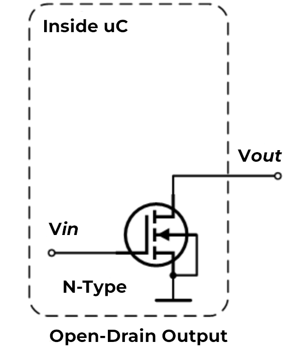
What it is: An open-drain pin is like a switch that can only connect to ground (0V) or disconnect completely. Think of it like a light switch that can only turn the light off or leave it “floating” - it cannot actively turn the light on by itself.
How it works: When the pin is active, it connects to ground (pulls the voltage down to 0V). When inactive, it simply disconnects and lets other components control the voltage on that wire.
Why it matters for 3D printers/CNC: Open-drain is useful when multiple devices need to share the same signal wire. For example:
- Multiple endstops on one pin: If you wire several endstop switches in series, they can all share one input pin using open-drain. When any switch triggers, it pulls the signal to ground.
- Shared alarm signals: When multiple devices need to signal an error condition on the same wire.
- Level shifting: When connecting 5V devices to 3.3V pins, open-drain lets you safely interface between different voltage levels.
When to use it:
Use open-drain (o) when you need to connect multiple switches or sensors to a single pin, or when interfacing with devices that expect open-collector/open-drain outputs.
Pull-Up Mode (^)
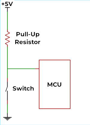
What it is: A pull-up resistor is like a weak spring that gently pulls the pin voltage up to 3.3V when nothing else is controlling it. It’s the default mode for most pins on the Smoothieboard.
How it works: Inside the microcontroller chip, there’s a resistor (typically around 50kΩ) connected between the pin and the 3.3V power supply. This resistor is “weak” - any external signal can easily override it. When you connect a switch or sensor that pulls the pin to ground, it wins over the pull-up resistor.
Why it matters for 3D printers/CNC: Pull-up mode is the standard way to connect switches and sensors:
- Endstop switches: When the switch is open (not triggered), the pull-up keeps the pin at 3.3V (high). When the switch closes, it connects the pin to ground, reading as 0V (low).
- Thermistor connections: Many temperature sensors work with pull-up resistors to create a voltage divider.
- Simple wiring: You only need two wires to your switch - one to the pin and one to ground. No separate power wire needed.
When to use it:
Use pull-up (^) for most switches, buttons, and sensors. This is the default and works for the majority of inputs on a 3D printer or CNC mill. If you don’t specify a modifier, the pin automatically uses pull-up mode.
Pull-Down Mode (v)
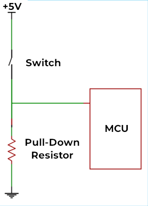
What it is: A pull-down resistor is the opposite of pull-up - it’s like a weak spring that gently pulls the pin voltage down to 0V (ground) when nothing else is controlling it.
How it works: Instead of connecting to 3.3V, the internal resistor connects between the pin and ground. The pin reads as 0V (low) by default, and only reads high (3.3V) when something actively drives it high.
Why it matters for 3D printers/CNC: Pull-down is less common but useful in specific situations:
- Active-high sensors: Some sensors output 3.3V when triggered and disconnect when not triggered. Pull-down ensures the pin reads 0V when disconnected.
- Normally-closed switches: If you’re using a switch that’s closed by default and opens when triggered, pull-down can simplify your wiring.
- Positive logic preference: When you want the pin to read “low” in the idle state and “high” when activated.
When to use it:
Use pull-down (v) when connecting sensors or switches that provide a positive voltage when active, or when you specifically want the opposite behavior of pull-up mode. This is relatively rare in typical 3D printer setups.
Repeater Mode (@)
What it is: Repeater mode is a hybrid that tries to “remember” the last signal it saw and weakly hold it there. It acts like both a pull-up and pull-down at the same time, maintaining whatever state the pin was last in.
How it works: The pin has circuitry that detects whether the last signal was high or low, then uses a weak resistor to keep it in that state. If the pin was pulled high, it acts like a pull-up. If it was pulled low, it acts like a pull-down. It “repeats” the last state it saw.
Why it matters for 3D printers/CNC: Repeater mode is useful in specific edge cases:
- Long wire runs: When you have very long cables (several meters) that might pick up electrical noise, repeater mode helps maintain signal stability.
- Floating inputs: When a pin might be disconnected temporarily but needs to maintain its last known state.
- Reducing noise: The weak holding force helps filter out brief noise spikes on the wire.
When to use it:
Use repeater mode (@) when you have long cables prone to noise, or when you need a pin to maintain its state even when the signal source briefly disconnects. This is the least commonly used mode in typical 3D printer or CNC setups - most users will never need it.
^) or pull-down (v) modes. Do not enable repeater mode simply because you think it will "make things better" - it is designed for very specific edge cases and is rarely needed in typical configurations.
Combining Multiple Modifiers
Important: You can use multiple modifiers on the same pin by placing them one after another. The pin configuration system allows you to combine different flags to achieve exactly the behavior you need.
Syntax:
my_pin_name 2.11!o^
In this example, pin
my_pin_name PC7!o^
In this example, pin PC7 is configured with:
!- Inverted outputo- Open-drain mode^- Pull-up enabled
Common Useful Combinations
Here are some practical combinations you might use in your 3D printer or CNC setup:
1. Inverted with Pull-up (!^)
endstop_pin 1.24!^
endstop_pin PA5!^
This is extremely common for endstops. The pull-up keeps the pin high (3.3V) when the switch is open, and the inversion means the firmware reads this as “not triggered.” When the switch closes, the pin goes to ground, and the inversion makes the firmware read it as “triggered.”
Why it’s useful: Many endstop configurations expect the opposite logic from what the hardware naturally provides. This lets you match your firmware expectations without rewiring.
2. Open-drain with Pull-up (o^)
shared_alarm_pin 2.11o^
shared_alarm_pin PC7o^
This creates a “wired-OR” configuration where multiple devices can signal on the same wire. Each device uses open-drain to pull the line low when active, and the pull-up resistor keeps it high when no device is signaling.
Why it’s useful: You can connect multiple safety sensors (like door switches, emergency stops, or temperature alarms) to a single pin. Any sensor triggering will pull the pin low.
3. Inverted Open-drain (!o)
output_pin 1.18!o
output_pin PB8!o
This inverts an open-drain output, which can be useful when controlling devices that expect active-high signals while using open-drain for level shifting.
Why it’s useful: When interfacing with 5V logic devices from your 3.3V Smoothieboard, you can use open-drain with a pull-up resistor to 5V on the other device. The inversion lets you maintain the expected logic levels.
4. No Pull with Invert (!-)
external_driver_pin 2.5!-
external_driver_pin PD12!-
Disables internal pull resistors and inverts the signal. This is useful when external hardware provides its own pull resistors and you need inverted logic.
Why it’s useful: Some external stepper drivers or relay boards have their own pull-up or pull-down resistors. Using - prevents conflicts between internal and external resistors, and ! adapts the logic level.
5. Pull-down with Invert (!v)
sensor_pin 1.29!v
sensor_pin PE6!v
Uses pull-down to keep the pin low by default, then inverts the reading. This means the firmware sees “high” when nothing is connected and “low” when the sensor activates and pulls the pin high.
Why it’s useful: Some active sensors output a positive voltage when triggered. Pull-down keeps noise low when disconnected, and the inversion can match your firmware’s expected logic.
Important Notes on Combining Modifiers
- Order doesn’t matter -
!o^and^o!ando!^all do the same thing - Conflicting modifiers - Don’t combine pull-up (
^) and pull-down (v) on the same pin, or pull-up (^) with no-pull (-). Only use one pull mode at a time. - Logical combinations - Think through what each modifier does and make sure they work together logically
- Test your setup - When using multiple modifiers, always test that the pin behaves as expected before relying on it for critical functions like endstops or safety sensors
Quick Reference: Common Combinations
| Combination | Config | Use Case |
|---|---|---|
| Inverted pull-up | !^ |
Endstops with reversed logic |
| Open-drain + pull-up | o^ |
Multiple sensors on one pin |
| Inverted open-drain | !o |
Level shifting with inverted logic |
| Inverted no-pull | !- |
External pull resistors with reversed logic |
| Inverted pull-down | !v |
Active-high sensors with reversed logic |
Default Pin Assignments
This table shows the default pin assignments for common functions:
| Function | Pin | Notes |
|---|---|---|
| X Step | Alpha stepper | |
| X Dir | Alpha stepper | |
| Y Step | Beta stepper | |
| Y Dir | Beta stepper | |
| Z Step | Gamma stepper | |
| Z Dir | Gamma stepper | |
| E0 Step | Delta stepper / Extruder | |
| E0 Dir | Delta stepper / Extruder | |
| Min X | X endstop | |
| Min Y | Y endstop | |
| Min Z | Z endstop | |
| Max X | X max endstop | |
| Max Y | Y max endstop | |
| Max Z | Z max endstop | |
| Hotend | PWM output | |
| Bed | PWM output |
Configuration Example
Here’s a typical configuration showing stepper and endstop pin assignments:
# Stepper and endstop configuration
alpha_step_pin                       2.0
alpha_dir_pin                        0.5!
alpha_en_pin                         0.4
alpha_min_endstop                    1.24^
alpha_max_endstop                    1.25^

beta_step_pin                        2.1
beta_dir_pin                         0.11!
beta_en_pin                          0.10
beta_min_endstop                     1.26^
beta_max_endstop                     1.27^
# Stepper and endstop configuration
alpha_step_pin                       PF0
alpha_dir_pin                        PF1!
alpha_en_pin                         PC0
alpha_min_endstop                    PG0^
alpha_max_endstop                    PG3^

beta_step_pin                        PF2
beta_dir_pin                         PF3!
beta_en_pin                          PC3
beta_min_endstop                     PG1^
beta_max_endstop                     PG4^
Summary:
- Pull-up (
^) - Default, best for switches and sensors (pin high by default, goes low when triggered) - Pull-down (
v) - Opposite of pull-up (pin low by default, goes high when triggered) - Open-drain (
o) - For sharing pins between multiple devices or level shifting - Repeater (
@) - For long cables or maintaining state (rarely needed)
Controlling with G-codes
By default, Smoothie will not heat anything. That could be a dangerous thing to do unwatched.
You have to send G-codes to turn your heater on and off, set a given temperature etc.
There is a set of widely used G-codes corresponding to different usual actions (for example setting the hotend temperature is
But as you are defining your own custom temperature controller, you have to choose what gcode will be used to control it, Smoothie doesn’t know what exactly it’s controlling.
So for example if this is a hotend, it will look something like this for the “standard” gcodes:
V1 Configuration:
temperature_control.hotend.set_m_code            104
temperature_control.hotend.set_and_wait_m_code   109
V2 Configuration:
[temperature control]
hotend.set_m_code = 104
hotend.set_and_wait_m_code = 109
set_m_code is used to set a given temperature, and continue running Smoothie immediately. set_and_wait_m_code is used to set a given temperature, and then pause Smoothie until that temperature is reached.
Reading with G-code
There is a single g-code used to read temperature for all the temperature_control modules at the same time:
But it has to have a way to tell you what temperature corresponds to what specific module.
There is a standard format for this which was used before Smoothie and still is today:
ok T:22.1 /0.0 @0 B:22.5 /75.0 @210
Here T is the hotend, and B is the bed. This is a convention. But in your configuration, we have to specify which is which:
V1 Configuration:
temperature_control.hotend.designator T
V2 Configuration:
[temperature control]
hotend.designator = T
Bang Bang Control
The simplest form of heat control is called bang bang this simply turns the heater on or off depending on whether it is under or over the target temperature (plus some hysteresis). This is best used for high amp beds using a relay to turn it on and off.
to enable this form of control in the config define the following…
V1 Configuration:
temperature_control.bed.bang_bang            true            # set to true to use bang bang control rather than PID
temperature_control.bed.hysteresis            2.0              # set to the temperature in degrees C to use as hysteresis when
V2 Configuration:
[temperature control]
bed.bang_bang = true          # set to true to use bang bang control rather than PID
bed.hysteresis = 2.0          # set to the temperature in degrees C to use as hysteresis
Example: If you set your temperature to 50 degrees, and your hysterisis is 2 degrees, then the heaters will turn on if the temperature is below 48 degrees, and off if the temperature is above 52 degrees.
The default form of heater control is PID.
PID
Temperature Control PID
Why PID is Important
PID is crucial for stable temperature control.
Without PID, a simple way to control temperature would be:
- If temperature too cold, turn heater on
- If temperature too hot, turn heater off
But there is a big problem with that method.
Due to temperature not traveling instantly from the heater to the thermistor, when the thermistor reads a given temperature, the heater is already hotter than what the thermistor reads.
This overshooting is something we do not want.
It means reaching temperatures that could be undesirable, and it means you will not be able to correctly stabilize the temperature.
What is PID?
The solution to this is PID.
It uses some math, allowing us to correct those problems by turning the heater on and off in a smarter sequence.
PID stands for:
- Proportional - Responds to current error
- Integral - Responds to accumulated error over time
- Derivative - Responds to rate of change of error
Configuring PID Values
The P, I, and D factors are configured in your config file as follows:
V1 Configuration:
temperature_control.hotend.p_factor     100
temperature_control.hotend.i_factor     0.1
temperature_control.hotend.d_factor     100
V2 Configuration:
[temperature control]
hotend.p_factor = 100
hotend.i_factor = 0.1
hotend.d_factor = 100
Finding the Right Values
The really tricky thing is to find the right values for these 3 factors.
The default ones are most probably wrong for your setup.
So unless you have been given those values with your hardware, or you are a PID grand-master, you will need some help finding the optimal values.
PID Auto-Tuning
To auto-tune your PID values:
- Start the auto-tune process:
M303 E0 S200E0 specifies the hotend (useE1 ,E2 , etc. for other extruders)S200 is the target temperature (adjust to your typical printing temperature)
-
Wait for completion - The process will take several minutes as it cycles the heater and measures response
-
Review the results - The auto-tune will output the calculated PID values
-
Update your config - Add the new values to your config file
- Test - Heat to your target temperature and verify stability
Manual PID Tuning
If auto-tuning doesn’t work well for your setup, you can manually tune:
Starting Values
Begin with conservative values:
V1 Configuration:
p_factor = 100
i_factor = 0.1
d_factor = 100
V2 Configuration:
[temperature control]
hotend.p_factor = 100
hotend.i_factor = 0.1
hotend.d_factor = 100
Tuning Process
- Adjust P first:
- Too low: Slow to reach temperature, large oscillations
- Too high: Fast oscillations, unstable
- Then adjust I:
- Too low: Won’t eliminate steady-state error
- Too high: Overshoots, slow to stabilize
- Finally adjust D:
- Too low: More overshoot
- Too high: Very sensitive, noisy
Different Heater Types
Different heater configurations may require different tuning approaches:
High-Power Heaters
High-power heaters (like cartridge heaters) may need:
- Lower P values
- Higher D values
- Faster response times
Low-Power Heaters
Low-power heaters (like resistive wire) may need:
- Higher P values
- More integral action
- Slower response tuning
Heated Beds
Heated beds typically need:
- Much lower P values due to large thermal mass
- More integral action for steady-state
- Lower D values due to slow thermal response
Troubleshooting PID Issues
Temperature Oscillates
Symptom: Temperature swings up and down around target
Solutions:
- Reduce P factor
- Increase D factor
- Check for good thermal coupling between heater and thermistor
Slow to Reach Temperature
Symptom: Takes a long time to heat up
Solutions:
- Increase P factor
- Check PWM frequency settings
- Verify heater power is adequate
Overshoots Temperature
Symptom: Temperature goes past target then settles
Solutions:
- Reduce P factor
- Increase D factor
- Reduce I factor
Won’t Stabilize
Symptom: Can’t maintain steady temperature
Solutions:
- Increase I factor slightly
- Check for environmental factors (drafts, etc.)
- Verify thermistor is working correctly
Advanced Configuration
PWM Frequency
The PWM frequency can affect PID performance:
V1 Configuration:
temperature_control.hotend.pwm_frequency 1000
V2 Configuration:
[temperature control]
hotend.pwm_frequency = 1000
Higher frequencies (1000-4000 Hz) are typically better for solid-state relays and MOSFETs.
Bang-Bang Mode
For very simple setups, you can disable PID entirely:
V1 Configuration:
temperature_control.hotend.bang_bang true
V2 Configuration:
[temperature control]
hotend.bang_bang = true
This uses simple on/off control. Not recommended for most applications.
Further Reading
- Temperature Control module documentation
- Thermistor configuration
- Heater configuration
M303 G-code documentation (see supported G-codes)
Safety Notes
- Never leave heaters unattended during PID tuning
- Ensure thermal runaway protection is enabled
- Monitor temperatures closely during tuning
- Have a fire extinguisher nearby
- Stop immediately if anything seems wrong
PID autotuning
PID Autotuning
Smoothie can automatically tune (find) your P, I, and D factors using a process described here.
Here is an example of the G-code command used to launch PID autotune:
E0 is the number of the heater or bed temperature control module, determined by the order that they appear in the config file. Here it would be 0 for the hotend, and 1 for the bed.S190 is the temperature to autotune for. Use the temperature you will be using your heater at in real life. For a hotend here we use 190°C.
When you run the command, tuning begins:
Target: 190.0
Start PID tune, command is M303 E0 S190
T: Starting PID Autotune, M304 aborts
ok
T:  21.3/190.0 @80 1 0/8
T:  22.0/190.0 @80 1 0/8
T:  22.3/190.0 @80 1 0/8
T:  22.1/190.0 @80 1 0/8
Etc...
It continues for 3 to 8 cycles, heating up, cooling down. Then:
Cycle 4: max: 246.189, min: 227.627, avg separation: 0.418274
	Ku: 34.9838, Pu: 39.85
	Trying:
	Kp:  21.0
	Ki: 1.053
	Kd:   105
PID Autotune Complete! The settings above have been loaded into memory, but not written to your config file.
Now edit your configuration to use those three values (
Alternatively, you can also enter the following G-code:
Which will save the configuration values automatically in a configuration override file.
Learn more about configuration overrides here.
If sent over the web, the answers will accumulate in Smoothie's RAM and may crash it.
Fine Tuning
Temperature Control Fine Tuning
This page provides tips for fine-tuning temperature control settings in Smoothie.
Common Scenarios
Using a 12V Heater on a 24V System
You need to set
V1 Configuration:
temperature_control.hotend.max_pwm 64
V2 Configuration:
[temperature control]
hotend.max_pwm = 64
Fixing Temperature Overshoot (10°C or More)
If you are getting 10°C or more initial overshoot of temperature, you can set
V1 Configuration:
temperature_control.hotend.i_max 128
V2 Configuration:
[temperature control]
hotend.i_max = 128
Setting Maximum Safe Temperature
To avoid accidental setting of too high a temperature, you can set
This will ignore any setting of temperatures that are higher than this and instead set the temp to
It will also trigger a shutdown if this temperature is exceeded.
V1 Configuration:
temperature_control.hotend.max_temp 230
V2 Configuration:
[temperature control]
hotend.max_temp = 230
Related Documentation
For more information on temperature control, see:
- Temperature Control Module - Main temperature control documentation
- PID Tuning - Detailed PID tuning guide
- Configuration Options - All configuration options
Safety
This module controls temperature by actuating heating elements. Heat, if left unchecked, causes fire.
Fires are painful, expensive, and can even cause death.
You definitely should set up as many safety features as you can, even those that are disabled by default. This section explains how to do so.
For an example see here.
This chapter covers all of the safety features, and how to set them up if needed.
Thermistor disconnect
If a thermistor is disconnected from its thermistor input (cable gets cut, connector falls), Smoothie can detect the problem by itself, as this causes a recognizably different input.
When this happens, Smoothie will detect the problem, turn off all heaters, and enter the HALT state. It will also show you the following message:
Temperature reading is unreliable on T, HALT asserted - reset or M999 required
You need to solve the issue, and then either reset the board or issue the
You do not need to do anything to activate this safety check.
Watchdog
The watchdog is a peripheral inside the microcontroller. Smoothie must tell it « Hey, I’m alive and I have not crashed » on a regular basis.
If Smoothie stops doing that, the watchdog knows Smoothie has crashed, and resets the board, which turns all heaters off.
This ensures that if the firmware crashes, your board’s heaters turn off, and everything is safe.
You do not need to do anything to activate this, it is on by default.
Maximum temperature detection
You activate this safety check (and you should) by adding the following to your configuration:
V1 Configuration:
temperature_control.module_name.max_temp 300
V2 Configuration:
[temperature control]
module_name.max_temp = 300
Once this is set, it will be impossible to set temperatures higher than the
Also, if the temperature reaches this
Error: MINTEMP or MAXTEMP triggered on T. Check your temperature sensors!
HALT asserted - reset or M999 required
You need to solve the issue, and then either reset the board or issue the
The most likely cause for this problem is that a heater mosfet is stuck being always active. If this is the case, Smoothie cannot control that heater anymore, and nothing the firmware can do can solve the issue, and you are on your way to a fire.
This is why you need to give Smoothie a second way to cut power: either by having a signal that allows you to turn the power supply off, or a solid-state relay capable of cutting all power to all mosfets. See documentation below for how to achieve this.
Runaway detection
We call “temperature runaway” a phenomenon where Smoothie tries to control temperature, but for some reason the temperature increases out of control.
There are several ways this can happen:
- The thermistor is disconnected from the heater block, so the thermistor is reading room temperature, and keeps heating to try to reach its target.
- The mosfet or solid-state relay controlling the heater is stuck always letting power pass through, this causes temperature to increase even when Smoothie does not ask for temperature to increase.
NOTE This is now enabled by default in newer versions of edge, the timeout is set pretty high (900 seconds), it can be disabled by setting the values below to 0.
Initial heat-up runaway detection
To detect if the thermistor is disconnected during the initial heat-up (temperature increasing until it reaches its target), we need to define how long it should take for temperature to increase to the target. And if the temperature takes too long to reach this target, we know something is wrong (likely the thermistor is detached from the heating element).
To configure this value, we first need to ask the machine to heat-up, and use a timer to know how long it takes. For example, a given hotend could take 100 seconds to heat up. Then, we add a margin to this, for example 20%, and we say that if the hotend takes more than 120 seconds to heat up, something is wrong.
Now that you have a reasonable safety value, add the runaway_heating_timeout option to your configuration file:
V1 Configuration:
temperature_control.module_name.runaway_heating_timeout 120 # max is 4088 seconds
V2 Configuration:
[temperature control]
module_name.runaway_heating_timeout = 120  # max is 4088 seconds
Now, if heating ever takes longer than 120 seconds, Smoothie will know there is a problem, enter HALT state, turn off heaters, and show the following message:
Error: Temperature too long to be reached on T, HALT asserted, TURN POWER OFF IMMEDIATELY - reset or M999 required
You can disable this by setting it to 0.
Please note that if your PID settings are not correctly tuned, this can get activated by accident because of the “swings” un-tuned temperature curves can have. Please tune your PID settings before activating this feature.
If the Smoothieboard is being a bit too strict with detecting the temperatures, you can add runaway_error_range as a parameter (optional), it is 1° by default meaning acceptable temperature detected can be +/- 1° of the set temp. If your printer tends to not stick close enough to the right temperature, increase this value. It only applies to the heat up and cool down timeouts.
runaway_cooling_timeout then understand that if you set a bed temp when the bed is already hotter than the setting it will need to cool down within the time period you set.If the bed has a lot of thermal mass then this may take a long time or actually never happen, and a timeout will occur eventually.
This is why it is disabled by default.
However, if you do reduce the bed temperature during a print you MUST set this value otherwise you will get a runaway detection error if the new temp is lower than the current temp.
This is also true of setting the hotend temperature lower while printing, then you also need to set this timeout correctly.
Out of range runaway detection
This safety feature allows to detect if the current temperature