Using the Touchprobe
About Touchprobes
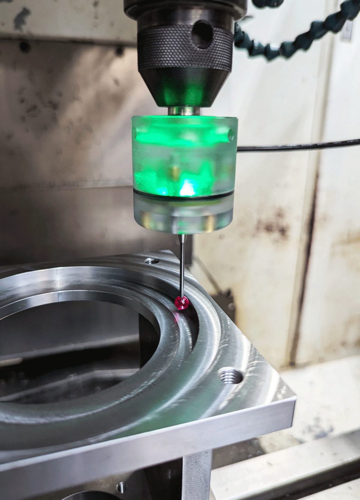
Example of a CNC touchprobe
Currently, the only operation regarding touchprobes supported by this module is
Important limitation: Coordinated moves are not supported.
This means only moves along a single axis will work.
Basic Usage Examples
Simple Probe Move
This will move to Z-10 and stop when a touch happens during that move:
G90
G31 Z-10 F150
G90 - Absolute positioning modeG31 - Probe move command- Z-10 - Move to Z position -10
- F150 - Feed rate of 150 mm/min
Two-Stage Probe (Fast then Slow)
This will probe at a fast speed, retract, probe at a slow speed, and report the position:
G91
G31 Z-10 F300
G0 Z0.2
G31 Z-0.3 F50
M114
What each line does:
G91 - Switch to relative positioningG31 Z-10 F300 - Fast probe down 10mm at 300 mm/minG0 Z0.2 - Retract 0.2mmG31 Z-0.3 F50 - Slow probe down 0.3mm at 50 mm/minM114 - Report current position
In addition to the
Configuration
The touchprobe module has the following configuration values (the values shown are defaults):
touchprobe_enable                   false              # enables/disables the module (other values ignored if false)
touchprobe_log_enable               false              # should the touches be logged to file
touchprobe_logfile_name             /sd/probe_log.csv  # location of the log file
touchprobe_log_rotate_mcode         0                  # adds a spacer to logfile if Mxxx is issued
touchprobe_pin                      nc                 # selects the pin where the probe is connected
touchprobe_debounce_count           100                # reports touch if probe active for this many ticks (prevents false positives)
Configuration Details
| Parameter | Description |
|---|---|
touchprobe_enable |
Must be set to true to use the module |
touchprobe_log_enable |
Set to true to log all probe touches |
touchprobe_logfile_name |
Path to log file (must be on SD card) |
touchprobe_log_rotate_mcode |
M-code number to insert spacer in log |
touchprobe_pin |
Input pin for probe signal |
touchprobe_debounce_count |
Higher values = more noise resistance but slower response |
Using Log Files
The log file is an easy way to create point clouds of the probed objects.
- Due to bugs in mbed, the log file isn't created automatically
- You must create the file first and restart Smoothie to update the file-handle properly
- Properly unmount (safely remove) the SD card before logging
- The file-system is dual-mounted by your OS and Smoothie, which can cause desynchronization
If you forget to safely remove the SD card, try to remount it afterward.
Most of the time, no data loss will happen.
Convert to Stanford PLY File
It’s very easy to convert the logfile to a PLY file, which is supported by most point cloud applications.
Note: This only works if there are no spacers in the file that are generated by the “log-rotation” M-code.
Conversion Steps
- Count the points - Find out how many points have been logged
- On Linux/Mac: Use
wc -l filename.csv - On Windows: Open in a text editor and check line count
- On Linux/Mac: Use
- Create the PLY header:
ply format ascii 1.0 comment smoothie cloud element vertex xxxxxxxx property float x property float y property float z element face 0 property list uchar int vertex_indices end_header -
Replace
xxxxxxxxwith the number you found in step 1 -
Prepend the header to your log file data
-
Save with .ply extension
- You’re done! Open in any point cloud viewer
Finding the Center of Round Objects
A common CNC task is finding the center of circular holes or bosses.
Method

Diagram showing probe points for finding center
Steps
-
Probe along the Y-axis for P1 and P2 (opposite sides)
-
Calculate the center between them:
P3 = (P1.x, P1.y + (P2.y - P1.y) / 2)
- Probe along the X-axis for P4 and P5
- Make sure the Y-axis is positioned at P3.y
-
Calculate the center between them:
M = (P4.x + (P5.x - P4.x) / 2, P3.y)
- M is the center of the round object
Alternatives
Since this module is deprecated, consider using:
- ZProbe module - Modern, actively maintained probing system
G30 command - Built-in probing command- Leveling strategies - For bed leveling and surface mapping