Probing with Smoothie
A probe is a switch (much like an Endstop) used to find where something is located automatically.
Smoothie will use it to move until the probe is “triggered” and stop there.
It can be used on CNC mills to:
- Find the length of a tool and how far its bottom is from the 0 position in Z
- Find the touching point between the workpiece and the tool
It can be used on 3D printers to:
- Find the touching point between the actuator and the bed
- Calibrate Delta geometry
- Do grid-based bed leveling to compensate for bed height irregularities
Different strategies are useful for different geometries of machines, click on one to go to it:
- For Delta machines, you can do grid leveling and calibration
- For Cartesian machines, you can do grid leveling or three-point leveling
NOTE: When
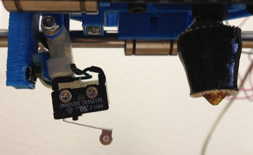
Making the probe retractable allows the probe not to be in the way of the plastic when it is not used.
Hardware requirements
You will need a probe switch attached to the machine’s actuator, or a bed able to trigger an end stop input when the hotend touches it. A point detection is best as the actual position is important for probing. (proximity probes are suboptimal as they do not detect the point position).
A bit more: You have two choices:
- Configure your probe as an endstop (in the endstop module), in which case you can use
G28 to use it to seek the bed, but you can’t use it in the zprobe module - Configure your probe as a probe (in the probe module), in which case you can’t use it with
G28 (the endstop module) to seek the bed, but you can use it withG30 to seek the bed, and you can use it withG31 /G32 etc to level/calibrate (this is likely what you want to do).
The point is you configure your sensor as either a probe or an endstop, not both. You can still use it for both leveling/calibration and bed seeking, it’s just that if it’s a probe (and not an endstop), you use a different Gcode (
Types of probes
Sensor Types
When setting up endstops and probes for your CNC machine or 3D printer, choosing the right sensor type is crucial for reliable operation.
Here is a table of the common sensor types, with their pros, cons, and our advice:
| Type | Uses | Pros | Cons | Our rating | Advice |
|---|---|---|---|---|---|
| Mechanical switch | Endstops, retractable Z-probes | Cheap, very durable, very precise/repeatable | None | This is the simplest, and also by chance the best sensor. Don’t use anything else unless you have a very good reason to. Just getting a fancier sensor because it feels cool to do so, is most likely going to bite you in the back quickly. | |
| Optical switch | Endstops, retractable Z-probes | Cheap, durable, very precise/repeatable | Dust can block light path after some time | This can be used in place of mechanical switches in most situations, has similar advantages, and doesn’t produce any sound. | |
| Hall effect | Endstops, bed probe | Fairly cheap, non-contact, variable precision/repeatability | Requires magnets, which accumulates ambient metal dust, can lack repeatability | A fair non-contact option if contact is an issue in your setup. | |
| Inductive | Endstops, bed probe | Non-contact | Expensive, difficult to wire, substandard repeatability, 24-36V requirement, endstop input protection (voltage divider) required | You probably shouldn’t use these unless you have a very good reason. | |
| Capacitive | Endstops, bed probe | Non-contact, can be used with glass bed | Expensive, difficult to wire, substandard repeatability, 24-36V requirement, endstop input protection (voltage divider) required | You probably shouldn’t use these unless you have a very good reason. | |
| Force sensitive resistor (FSR) | Bed probe | Can be used under a glass bed, non-contact, can be very reliable if set up correctly | Difficult to set up correctly, finicky, expensive, analog meaning it requires an adapter, more complex to wire | You probably shouldn’t use these unless you have a very good reason. | |
| IR probes | Z probe, bed probe | Non-contact | Expensive, analog meaning it requires an adapter, terrible repeatability/accuracy, more complex to wire | You probably shouldn’t use these unless you have a very good reason. | |
| Bltouch | Retractable Z-probes | Cheap, very durable, very precise/repeatable, retractable (equivalent to a servo-mounted mechanical switch) | None, other than the added complexity of retracting | The mechanical switches are the best sensors by far, but this is very similar, essentially emulating a servo-mounted mechanical switch. |
Recommendations
For retractable Z-probes, BLTouch sensors provide excellent performance and reliability.
Avoid complex sensors unless you have a specific requirement that justifies the added complexity and cost.
Additional Resources
The Reprap probe page also has information on this that you might find helpful.
Configuration
Add the following to the config file:
gamma_min_endstop            nc                 # normally 1.28. Change to nc to prevent conflict, not needed on Azteeg X5

zprobe.enable                true               # set to true to enable a zprobe
zprobe.probe_pin             1.28!^             # pin probe is attached to if NC remove the !, Azteeg X5 this is 1.29
zprobe.slow_feedrate         5                  # mm/sec probe feed rate
#zprobe.debounce_ms          1                  # set if noisy
zprobe.fast_feedrate         100                # move feedrate
zprobe.probe_height          5                  # how much above bed to start probe NB only needed for G32 on delta
zprobe.return_feedrate       0                  # feedrate after a probe, default 0 is double of slow_feedrate (mm/s)
zprobe.max_z                 200                # maximum default travel for the probe command, will use gamma_max if not defined
[endstops.gamma_min]
pin = nc                 # normally 1.28. Change to nc to prevent conflict

[zprobe]
enable = true               # set to true to enable a zprobe
probe_pin = 1.28!^          # pin probe is attached to if NC remove the !
slow_feedrate = 5           # mm/sec probe feed rate
#debounce_ms = 1            # set if noisy
fast_feedrate = 100         # move feedrate
probe_height = 5            # how much above bed to start probe NB only needed for G32 on delta
return_feedrate = 0         # feedrate after a probe, default 0 is double of slow_feedrate (mm/s)
max_travel = 200            # maximum default travel for the probe command
In V1, you need to set the endstop pin to nc (not connected) to avoid conflicts when using the same pin for the probe. For example, gamma_min_endstop nc prevents conflicts with zprobe.probe_pin 1.28!^.
V2 Improvement: ZProbe no longer conflicts with endstop pins. You can use any available GPIO pin for the probe without worrying about endstop assignment conflicts.
slow_feedrate is the speed the probe moves down to find the bed, it returns (probe up) at 2 * slow_feedrate or return_feedrate.
fast_feedrate is only used for any XY moves done during probing.
First test the zprobe with
If there are multiple leveling strategies selected the Pn parameter will select which one to send leveling codes to, 0 being the first defined one, 1 the second and so on. For example,
There are several
| Set Probe feedrates slow/fast/return (mm/sec) | |
| Set Probe max_z (mm) | |
| Set Probe height (mm) | |
| Temporarily invert the sense of the probe pin (Not saved with |
leveling-strategy.xxx.enable is set to true this enables one of the bed leveling strategies described below.
NOTE that most leveling strategies cannot be run from a web interface. If using network, use telnet to run them, or use the USB serial port.
Configuration options
| V1 Setting | V2 Setting | Description |
|---|---|---|
| Enables the Z-probe module. When set to true, the probe module is loaded and all probing features become available. Set to false to disable probing entirely and free memory if not using a probe. | ||
Defines the GPIO pin connected to the probe signal. Use ! suffix to invert logic (normally-closed vs normally-open) and ^ to enable internal pull-up resistor. Example: 1.28!^ means pin 1.28 with inverted logic and pull-up enabled. |
||
| Speed at which the probe approaches the bed during actual probing moves, in millimeters per second. Slower speeds improve accuracy but increase total probing time. Typical values: 5-10 mm/s. | ||
| Travel speed between probe points and for initial rapid approach moves, in millimeters per second. Does not affect probing accuracy but reduces total time for multi-point bed leveling operations. Typical values: 50-200 mm/s. | ||
| Speed when retracting from a probe point, in millimeters per second. When set to 0 (default), automatically calculates as slow_feedrate × 2 for faster retraction without sacrificing accuracy. | ||
| Probe signal debounce time in milliseconds. The probe signal must remain continuously triggered for this duration before being considered a valid trigger. Set to 1 or 2 if your probe is noisy and gives false readings. Higher values reduce false triggers but may affect accuracy. | ||
| Height above the bed to position the probe before starting each probing move, in millimeters. Once the bed's approximate height is known (after first probe or homing), subsequent probes start from this height. Typical values: 5-10 mm. | ||
| Maximum distance the probe will travel downward before giving up on a probe attempt, in millimeters. Safety feature to prevent crashes if probe fails to trigger. If not defined, uses gamma_max value from endstop configuration. Set to slightly less than your build height. | ||
| Time to wait before starting each probe move, in seconds. Allows mechanical settling after XY positioning and before Z probe begins. Particularly useful for piezo Z-probes to avoid false triggers from vibration. Typical values: 0.1-0.5 seconds. | ||
| Probe in +Z direction instead of -Z direction. Used for specialized machine setups where the probe moves upward to find the surface rather than downward. Rarely needed for standard configurations. | ||
G-code command(s) to run before each probe point. Used for deployable probes like BLTouch/3DTouch that need to extend or deploy before probing. Multiple commands can be separated by semicolons. Example: M280 S10 to deploy BLTouch pin. |
||
G-code command(s) to run after each probe point. Used for deployable probes like BLTouch/3DTouch that need to retract after probing. Multiple commands can be separated by semicolons. Example: M280 S90 to retract BLTouch pin. |
||
| — | Enables manual probe attachment mode for removable probes. When enabled, the machine moves to the mount_position and waits for the user to manually attach the probe before probing operations. V2 removed this feature. | |
| — | Position in machine coordinates where the machine moves and waits for manual probe attachment when m_attach is enabled. Specified as comma-separated X,Y,Z coordinates. Only used when m_attach is true. V2 removed this feature. |
Probing for linear delta machines
Delta calibration
Just run it and save the results.
It does not set the Z height, that can be done in several different ways as described later.
Make sure the config has delta_homing true set and that zprobe.max_z is set to about 20-30mm shorter than the distance to the bed, otherwise it will crash into the bed at high speed.
Also in the config set:
leveling-strategy.delta-calibration.enable   true            # basic delta calibration
leveling-strategy.delta-calibration.radius   100             # the probe radius
leveling-strategy.delta-calibration.initial_height 10        # height above bed to stop initial move
#the initial height above the bed we stop the initial move down after home to find the bed
#this should be a height that is enough that the probe will not hit the bed and is an offset from zprobe.max_z (can be set to 0 if zprobe.max_z takes into account the probe offset)
[leveling_strategy.delta_calibration]
enable = true            # basic delta calibration
radius = 100             # the probe radius
initial_height = 10      # height above bed to stop initial move
#the initial height above the bed we stop the initial move down after home to find the bed
#this should be a height that is enough that the probe will not hit the bed and is an offset from zprobe.max_travel (can be set to 0 if zprobe.max_travel takes into account the probe offset)
leveling-strategy.delta-calibration.radius should optimally be set such that the probe points are on the circumference of a circle that is equidistant from the center of the bed to the towers.This minimizes the effect one endstop has on the others when adjusted.
This will usually put the probe points close to the edge of the glass bed.
Calibration routine
Issuing the
It will cycle several times to converge on a good result.
If the result is good use
What will happen is it will home the probe down to find the bed, then home again then move down to 5mm above the bed (or whatever you set zprobe.probe_height to).
Then it will probe the three towers at the specified leveling-strategy.delta-calibration.radius from the center, and will print out the results, it will set the endstop trims and home, this will repeat 3-4 times, each time the difference between the three probes should get smaller, once it has completed 4 probes or the difference is under 0.03mm it will home one last time then probe the three points to confirm the calibration, then probe the center.
It will also adjust the delta radius (
Configuration options
| V1 Setting | V2 Setting | Description |
|---|---|---|
Enables the delta calibration strategy for automatically calibrating linear delta printer geometry. The strategy probes seven points (three at towers, three between towers, one at center) and adjusts endstop trim values and delta radius to minimize height differences. This strategy is specifically for delta kinematics and is automatically loaded for delta printers if no other strategy is specified. In v2, set zprobe.calibration to "delta". |
||
Radius in millimeters at which to probe the bed for delta calibration. This determines the size of the circular pattern formed by the seven probe points: three points at the tower positions on this radius, three points between towers on this radius, and one point at center (radius 0). The radius should be as large as possible while staying within the printable area. Default: 100 mm |
||
Absolute Z machine position in millimeters to move to after homing and before starting the initial bed probe. This height must be high enough that the probe will not hit the bed during the rapid descent phase. This is a critical safety parameter that prevents crashes during the first probe approach. Default: 10 mm |
Example configuration
To activate this leveling strategy, copy/paste the following to your configuration file and edit it accordingly:
leveling-strategy.delta-calibration.enable                true      # Set to true to enable the delta calibration leveling strategy.
                                                                    # This uses the probe to figure out the plane's tilt and arm's radius
                                                                    # in a delta machine
leveling-strategy.delta-calibration.radius                100       # Radius at which to probe the three points
leveling-strategy.delta-calibration.initial_height        10        # The initial height above the bed we stop the initial move down after home
                                                                    # to find the bed. This should be a height that is enough that the probe
                                                                    # will not hit the bed
Uses
These are the different ways to use the calibration routine:
| will probe the seven points on your bed, you can use this to see how well the bed is leveled. | |
| will probe the seven points on your bed, and output the data that can be fed into some offline least errors scripts to adjust tower offsets | |
| Does the full calibration sequence, endstop and delta radius | |
| Will only do delta radius calibration | |
| Will only do endstop calibration | |
| Will set the target to within 0.02mm | |
| Will keep the current endstop trim settings and check them, without K the trims are cleared to zero and a full calibration is performed | |
| will set the probe radius to 110.0 mm for this session | |
| saves the probe points | |
| displays the current settings |
Example use:
    G28 (Home XYZ)
    (Move Z at least 30mm away from the bed if it's not, and attach probe if you have a removable probe)
    G32 (Calibrate the machine)
    (Remove probe if you have a removable probe)
    M500 (to save probe results)
    G28 (Home XYZ)
    (Manually: jog down to touch the plate)
    M306 Z0
    M500 (to save homing offset)
    G28
    (Machine is now calibrated and knows its correct height above the bed)
This is by design as the calibration works solely on relative positions.
To be clear: there are no offsets in Smoothie, and they would not be useful as calibration is relative.
This can be confusing to Marlin users.
Just use it and you'll see.
Calibration failed to complete error, or the probe crashes into the bed on the initial probe, it usually means you need to increase the leveling-strategy.delta-calibration.initial_height config setting to a bigger value, try 10 or 20 or bigger.With the recent version it should move fast to just above the bed then move to the bed slowly, if it hits the bed on the first fast move then you need to set initial-height bigger.
See http://minow.blogspot.com/ for more details of calibrating a delta.

Nothing is perfect
Delta Grid Compensation
Probes delta_grid.size points in X and Y (total probes size * size) and stores the relative offsets from the 0,0 Z height. When enabled every move will calculate the Z offset based on interpolating the height offset within the grids nearest 4 points.
Should be used in conjunction with the delta calibration strategy above.
First calibrate with
delta-grid.radius specified should be at least as big as the largest X,Y position likely to be moved to.It gets very inaccurate if you try to print outside of the radius you specified.
Configuration
The strategy must be enabled in the config as well as zprobe.
leveling-strategy.delta-grid.enable true
The radius of the bed must be specified with…
leveling-strategy.delta-grid.radius 50
This needs to be at least as big as the maximum printing radius as moves outside of this will not be compensated for correctly
The size of the grid can be set with…
leveling-strategy.delta-grid.size 7
This is the X and Y size of the grid, it must be an odd number, the default is 7 which is 49 probe points
leveling-strategy.delta-grid.do_home true
This must be set on a Delta printer (although it should default to true).
If you are not using all 3 endstops (or prefer to home manually before
leveling-strategy.delta-grid.do_home false
[leveling_strategy.delta_grid]
enable = true         # Enable delta grid leveling
radius = 50           # Radius of the bed (needs to be at least as big as maximum printing radius)
size = 7              # X and Y size of grid (must be odd number, default 7 = 49 probe points)
do_home = true        # Must be set on Delta printer (defaults to true)
If you are not using all 3 endstops (or prefer to home manually before
[leveling_strategy.delta_grid]
do_home = false
do_home is set to false.
Optionally probe offsets from the nozzle or tool head can be defined with…
leveling-strategy.delta-grid.probe_offsets 0,0,0 # probe offsets x,y,z (Z should always be 0)
They may also be set with
So having a probe offset from the head will try to compensate for errors which are offset from where the head actually is.
There is no easy way to overcome this other than have the probe as close to the nozzle as possible.
If the saved grid is to be loaded on boot then this must be set in the config…
leveling-strategy.delta-grid.save true
Then when
If the grid size is different from the one in config it will NOT load.
If the radius is different, then the radius will be set to whatever was saved overriding the one set in config.
DO NOT call
Optionally an initial_height can be set that tell the initial probe where to stop the fast descent before it probes, this should be around 5-10mm above the bed
leveling-strategy.delta-grid.initial_height 10
Configuration options
| V1 Setting | V2 Setting | Description |
|---|---|---|
Enables the delta grid leveling strategy for height mapping across circular delta printer beds. The strategy probes a grid of points in a circular pattern (skipping corners outside the radius) and stores height offsets. During printing, the firmware interpolates between the nearest four grid points to calculate Z compensation for any XY position. In v2, set zprobe.leveling to "delta grid". |
||
Radius of the circular bed area to probe and compensate in millimeters. The grid probes a square region, but points outside this radius are skipped, creating a circular probe pattern. This radius should be at least as large as the maximum printing radius to ensure full bed compensation coverage. Default: 50 mm |
||
Grid size in both X and Y dimensions, determining the total number of probe points. A size of 7 creates a 7×7 grid = 49 potential probe points (points outside the radius are automatically skipped). Larger grids provide more accurate compensation but increase probing time significantly. Must be an odd number. Default: 7 |
||
Offset of the probe tip from the nozzle tip in X, Y, and Z dimensions. These offsets compensate for the physical displacement between where the probe triggers and where the nozzle actually is. Correct offsets are essential for accurate bed compensation. Format: X,Y,Z (default: 0,0,0) |
||
Absolute Z machine position in millimeters to move to after homing before starting the grid probe sequence. This safety parameter prevents the probe from crashing into the bed during the initial descent. Must be high enough to clear the bed surface. Default: 10 mm |
||
Automatically homes all axes before running the G31 grid probing sequence. Homing ensures the machine is at a known position before probing, which is essential for repeatable and accurate grid generation. Disable only if you want manual control over the homing process. Default: true |
||
Automatically saves M375 command to config-override when M500 is issued, causing the grid to be loaded from /sd/delta.grid on boot and compensation to be enabled automatically. This allows persistent bed leveling across power cycles without re-probing. Default: false |
||
Probe tolerance for repeatability checks and validation during grid creation. Used to validate that probe measurements are consistent and repeatable across multiple probes of the same point. Default: 0.03 mm |
||
| N/A (feature removed) | DEPRECATED - This setting is no longer supported and will produce an error if used. For square or rectangular beds, use the rectangular-grid strategy instead of delta-grid. |
Example configuration
To activate this leveling strategy, copy/paste the following to your configuration file and edit it accordingly:
leveling-strategy.delta-grid.enable               true     # The strategy must be enabled in the config, as well as the zprobe module.
leveling-strategy.delta-grid.radius               50       # Radius of the bed, must be specified. This needs to be at least as big as
                                                           # the maximum printing radius as moves outside of this will not
                                                           # be compensated for correctly
leveling-strategy.delta-grid.size                 7        # The size of the grid, for example, 7 causes a 7x7 grid with 49 points.
                                                           # Must be an odd number.
leveling-strategy.delta-grid.probe_offsets        0,0,0    # Optional probe offsets from the nozzle or tool head
leveling-strategy.delta-grid.save                 false    # If the saved grid is to be loaded on boot then this must be set to true
leveling-strategy.delta-grid.initial_height       10       # Optionally an initial_height can be set that tell the initial probe
                                                           # where to stop the fast descent before it probes, this should be
                                                           # around 5-10mm above the bed
[leveling_strategy.delta_grid]
enable = true               # The strategy must be enabled in the config, as well as the zprobe module.
radius = 50                 # Radius of the bed, must be specified. This needs to be at least as big as
                            # the maximum printing radius as moves outside of this will not
                            # be compensated for correctly
size = 7                    # The size of the grid, for example, 7 causes a 7x7 grid with 49 points.
                            # Must be an odd number.
probe_offsets = 0,0,0       # Optional probe offsets from the nozzle or tool head
save = false                # If the saved grid is to be loaded on boot then this must be set to true
initial_height = 10         # Optionally an initial_height can be set that tell the initial probe
                            # where to stop the fast descent before it probes, this should be
                            # around 5-10mm above the bed
Usage
| test probes in a grid pattern within the radius producing a map of offsets, this can be imported into a graphing program to visualize the bed ( |