LPC1769 Pin Usage
This page documents all pin assignments for the LPC1769 microcontroller on Smoothieboard.
Pin list
The following table shows all pin assignments on the LPC1769 microcontroller:
| ARM Pin | Smoothie Pin | mBed Pin | LPCXpresso Pin | Assignment | Comment |
|---|---|---|---|---|---|
| i2c1 sda | Internal I2C bus. Used for digipots and port expander. | ||||
| i2c1 scl | Internal I2C bus. Used for digipots and port expander. | ||||
| uart0 txd | Used for ISP programming of the bootloader and for debugging. | ||||
| uart0 rxd | Used for ISP programming of the bootloader and for debugging. | ||||
| alpha_en_pin | |||||
| alpha_dir_pin | |||||
| spi1 ssel | sdcard | ||||
| spi1 sck | sdcard | ||||
| spi1 miso | sdcard | ||||
| spi1 mosi | sdcard | ||||
| beta_en_pin | also i2c2 sda | ||||
| beta_dir_pin | also i2c2 scl | ||||
| spi0 sck | User spi port. used for rrd glcd | ||||
| spi0 ssel | User spi port. used for rrd glcd cs | ||||
| spi0 miso | User spi port. | ||||
| spi0 mosi | User spi port. used for rrd glcd | ||||
| - | gamma_en_pin | also i2c3 sda on lpcxpresso e2prom | |||
| - | gamma_dir_pin | also i2c3 scl on lpcxpresso e2prom | |||
| - | delta_en_pin | ||||
| - | delta_dir_pin | lpcxpresso led | |||
| hotend.thermistor_pin | |||||
| bed.thermistor_pin | |||||
| thermistor2 | |||||
| thermistor3 | |||||
| - | i2c0 sda | User i2c port. sd cd on rrd glcd adapter | |||
| - | i2c0 scl | User i2c port. sd cs2 on rrd glcd adapter | |||
| USB-D+ | |||||
| USB-D- | |||||
| eth txd0 | |||||
| eth txd1 | |||||
| eth tx en | |||||
| eth crs | |||||
| eth rxd0 | |||||
| eth rxd1 | |||||
| eth rx err | |||||
| eth ref clk | |||||
| eth mdc | |||||
| eth mdio | |||||
| led1 | h/w PWM capable. can be free if leds_disable is set true in config. |
||||
| - | led2 | can be free if leds_disable is set true in config. | |||
| led3 | h/w PWM capable. can be free if leds_disable is set true in config. |
||||
| led4 | h/w PWM capable. can be free if leds_disable is set true in config. |
||||
| - | 3rd small fet | spare on 3 and 4 driver boards | |||
| 3rd large fet | spare on 3 and 4 driver boards, h/w PWM capable |
||||
| - | alpha_min_endstop | h/w PWM capable |
|||
| - | alpha_max_endstop | ||||
| - | beta_min_endstop | h/w PWM capable |
|||
| - | beta_max_endstop | ||||
| - | gamma_min_endstop | ||||
| - | gamma_max_endstop | ||||
| spare | used for click button on rrd glcd | ||||
| spare | used for buzzer on rrd glcd | ||||
| alpha_step_pin | h/w PWM capable |
||||
| beta_step_pin | h/w PWM capable |
||||
| gamma_step_pin | h/w PWM capable |
||||
| delta_step_pin | h/w PWM capable |
||||
| psu.output_pin | h/w PWM capable |
||||
| bed.heater_pin | h/w PWM capable |
||||
| - | fan.output_pin | ||||
| - | hotend.heater_pin | ||||
| - | epsilon_step_pin | spare on 3 and 4 driver | |||
| - | USB soft connect | ||||
| - | ISP button | ||||
| - | spare | used for pause/kill/back pin on glcd | |||
| - | kill button | Hardwired in Bootloader as ISP button and in kill module as pause button | |||
| - | epsilon_dir_pin | spare on 3 and 4 driver | |||
| - | spare | used for encoder pin for all panels, h/w PWM capable |
|||
| - | spare | used for encoder pin for all panels, h/w PWM capable |
|||
| - | play/pause led | ||||
| - | epsilon_en_pin | spare on 3 and 4 driver cannot be used in opendrain |
The following pins are hardwired and would need to be changed in source code:
Some pins are also setup as outputs and changed in the Bootloader and those are not configurable, these pins are:
P0.* and P2.* can be setup as interrupt enabled pins.
The LPC1769 pin list does not apply to V2 Prime. See STM32H7 pin usage.
Pin Format Reference
V1 Pin Format: port.pin with optional modifiers
- Basic format:
1.24,2.0,0.11 - Pull-up modifier:
1.24^(enable internal pull-up) - Inverted logic:
1.24!(invert pin logic) - Open-drain:
2.0o(configure as open-drain) - Combined:
1.24^!(pull-up + inverted)
V2 Pin Format: Similar port.pin format with additional options
- Basic format:
PA.0,PB.5, or numeric1.24,2.0 - Named pins: Board-specific named pins may be available
- Modifiers: Similar to V1 (pull-up
^, inverted!, open-draino) - Check board-specific documentation for exact pin names and available features
Migration Guide: V1 to V2 Pin Configuration
This section shows real-world examples of converting V1 pin configurations to V2 format.
Stepper Motor Pin Configuration
# Alpha (X) axis motor configuration
alpha_step_pin                      2.0
alpha_dir_pin                       0.5
alpha_en_pin                        0.4

# Beta (Y) axis motor configuration
beta_step_pin                       2.1
beta_dir_pin                        0.11
beta_en_pin                         0.10
# Alpha (X) axis motor configuration
alpha_step_pin                      2.0
alpha_dir_pin                       0.5
alpha_en_pin                        0.4

# Beta (Y) axis motor configuration
beta_step_pin                       2.1
beta_dir_pin                        0.11
beta_en_pin                         0.10

# V2 maintains backward compatibility with numeric pin format
# Named pin aliases may be available depending on board
Endstop Configuration with Modifiers
# Min endstops with pull-up resistors
alpha_min_endstop                   1.24^
beta_min_endstop                    1.26^
gamma_min_endstop                   1.28^

# Max endstops inverted logic
alpha_max_endstop                   1.25!
beta_max_endstop                    1.27!
gamma_max_endstop                   1.29!
# Min endstops with pull-up resistors
alpha_min_endstop                   1.24^
beta_min_endstop                    1.26^
gamma_min_endstop                   1.28^

# Max endstops inverted logic
alpha_max_endstop                   1.25!
beta_max_endstop                    1.27!
gamma_max_endstop                   1.29!

# Modifier syntax remains the same in V2
Heater and Temperature Sensor Configuration
# Hotend configuration
temperature_control.hotend.heater_pin    2.7
temperature_control.hotend.thermistor_pin 0.23

# Heated bed configuration
temperature_control.bed.heater_pin       2.5
temperature_control.bed.thermistor_pin   0.24
# Hotend configuration
temperature_control.hotend.heater_pin    2.7
temperature_control.hotend.thermistor_pin 0.23

# Heated bed configuration
temperature_control.bed.heater_pin       2.5
temperature_control.bed.thermistor_pin   0.24

# Pin assignments remain compatible in V2
Fan and Switch Configuration
# Cooling fan
switch.fan.output_pin               2.6

# PSU control (inverted, open-drain)
switch.psu.output_pin               2.4!o

# Auxiliary outputs
switch.misc.output_pin              1.22
# Cooling fan
switch.fan.output_pin               2.6

# PSU control (inverted, open-drain)
switch.psu.output_pin               2.4!o

# Auxiliary outputs
switch.misc.output_pin              1.22

# Modifier combinations (!o) work the same in V2
Pin Format Comparison Table
The following table shows common pin assignments with V1 and V2 format side-by-side:
| Function | V1 Pin Format | Notes |
|---|---|---|
| Alpha Step | 2.0 |
Basic numeric format |
| Alpha Dir | 0.5 |
Port.pin notation |
| Alpha Enable | 0.4 |
Standard output |
| Alpha Min Endstop | 1.24^ |
With pull-up |
| Alpha Max Endstop | 1.25! |
Inverted logic |
| Hotend Heater | 2.7 |
PWM capable |
| Hotend Thermistor | 0.23 |
ADC input |
| Bed Heater | 2.5 |
PWM capable |
| Bed Thermistor | 0.24 |
ADC input |
| Fan Output | 2.6 |
Standard output |
| PSU Control | 2.4!o |
Inverted + open-drain |
| Spare I/O | 1.30^ |
With pull-up |
| LED | 1.18 |
PWM capable |
| Function | V2 Pin Format | Notes |
|---|---|---|
| Alpha Step | 2.0 or PA.0 |
Numeric or named format |
| Alpha Dir | 0.5 or PA.5 |
Board-dependent naming |
| Alpha Enable | 0.4 or PA.4 |
Check board docs |
| Alpha Min Endstop | 1.24^ |
Modifier syntax same |
| Alpha Max Endstop | 1.25! |
Inverted logic same |
| Hotend Heater | 2.7 |
PWM capable |
| Hotend Thermistor | 0.23 |
ADC input |
| Bed Heater | 2.5 |
PWM capable |
| Bed Thermistor | 0.24 |
ADC input |
| Fan Output | 2.6 |
Standard output |
| PSU Control | 2.4!o |
Modifiers work same |
| Spare I/O | 1.30^ |
Pull-up syntax same |
| LED | 1.18 |
PWM capable |
LPC176x ADC channels and pins
| Adc Channel | Port Pin | Pin Functions | Associated PINSEL Register |
|---|---|---|---|
| AD0 P0.23 | 0-GPIO, | 1-AD0[0], 2-I2SRX_CLK, 3-CAP3[0] | 14,15 bits of PINSEL1 |
| AD1 P0.24 | 0-GPIO, | 1-AD0[1], 2-I2SRX_WS, 3-CAP3[1] | 16,17 bits of PINSEL1 |
| AD2 P0.25 | 0-GPIO, | 1-AD0[2], 2-I2SRX_SDA, 3-TXD3 | 18,19 bits of PINSEL1 |
| AD3 P0.26 | 0-GPIO, | 1-AD0[3], 2-AOUT, 3-RXD3 | 20,21 bits of PINSEL1 |
| AD4 P1.30 | 0-GPIO, | 1-VBUS, 2- , 3-AD0[4] | 28,29 bits of PINSEL3 |
| AD5 P1.31 | 0-GPIO, | 1-SCK1, 2- , 3-AD0[5] | 30,31 bits of PINSEL3 |
| AD6 P0.3 | 0-GPIO, | 1-RXD0, 2-AD0[6], 3- | 6,7 bits of PINSEL0 * not available on Smoothieboard |
| AD7 P0.2 | 0-GPIO, | 1-TXD0, 2-AD0[7], 3- | 4,5 bits of PINSEL0 * not available on Smoothieboard |
V2 Prime uses the STM32H745 ADC mapping; see STM32H7 pin usage.
Pinout
Pinout
This page shows the pinout diagrams for the board.
Wiring Diagram
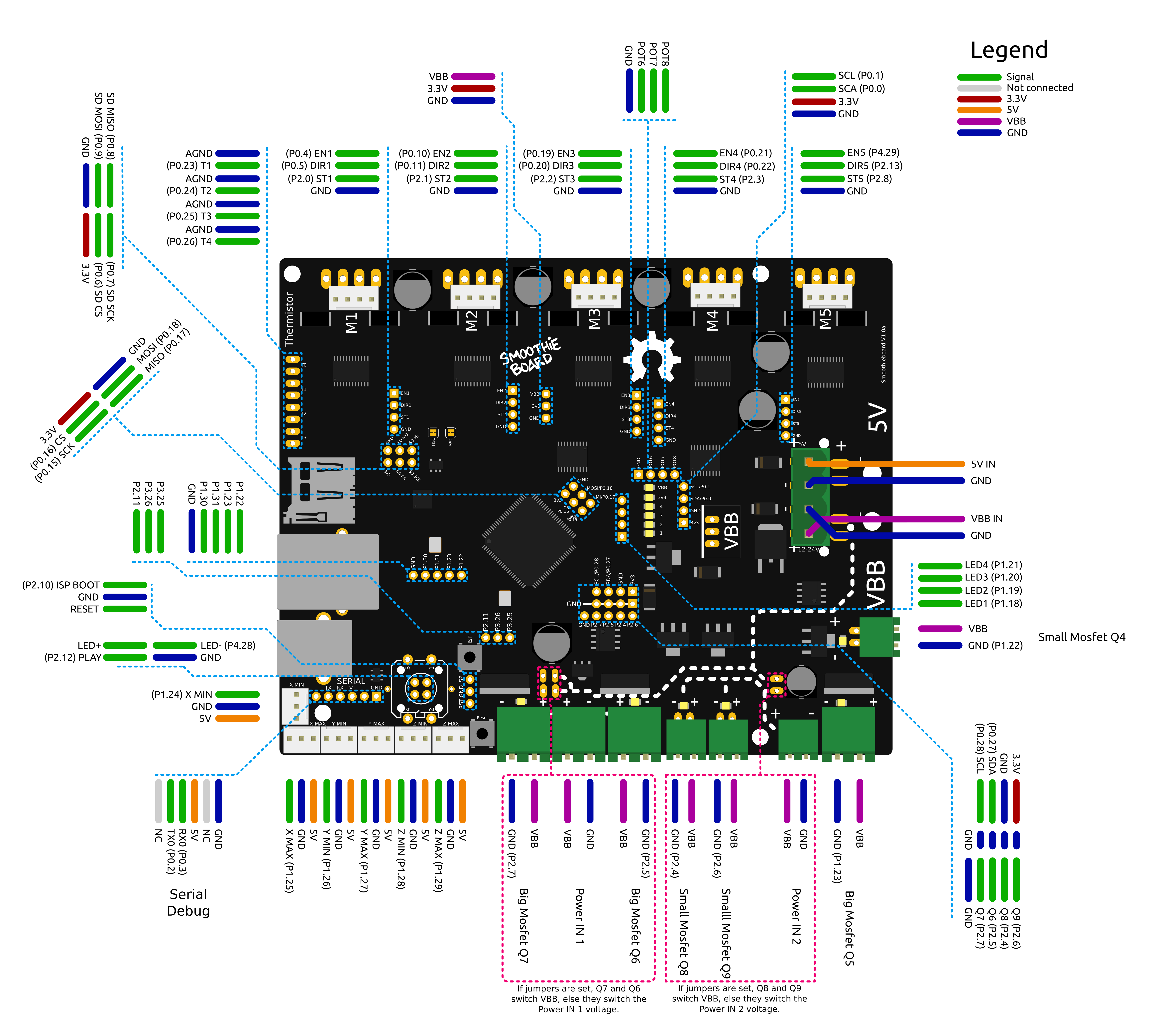
Smoothieboard wiring diagram - click to enlarge
Pin Capabilities
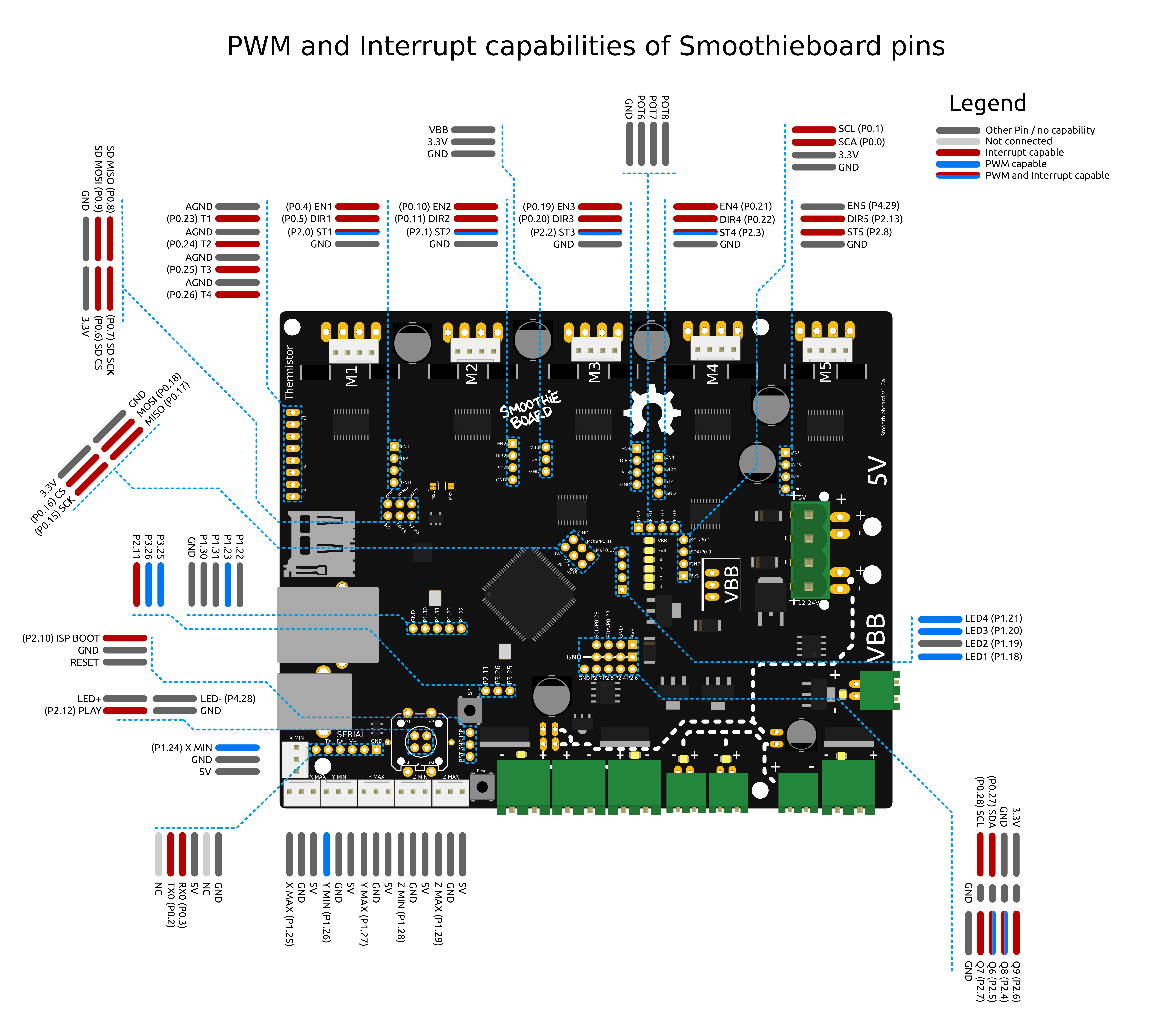
Smoothieboard pin capabilities - click to enlarge
View full size pin capabilities diagram
Also see the pin usage table for detailed information about each pin.
The V2 pinout diagrams are still being created. Check back soon for updated wiring and pin capability diagrams for V2 boards.
Important Notes
See STM32H7 pin usage for V2 Prime pin assignments.