Temporary comparison page: this is the reworked version. Open the current Endstops page in another tab to compare them side by side.
Endstops
It’s essentially just a switch
End-stops are small interrupters that you put at the end of each of your axes.
When you boot your machine up, Smoothie has no way of knowing the position of each axis.
When it starts a print, Smoothie moves the axis until it touches that interrupter, and when it is hit, it declares that that is position 0 for that axis. And does so for all axes.
More precisely, it declares the position configured for that endstop, which is usually 0. You can change that position when the machine’s origin is somewhere else.
This allows Smoothie to then precisely know where everything is relative to that initial position.
It is quite convenient as it saves you the hassle of actually moving the machine into that position when you want to start a print. Automation is great.
However, end-stops are not necessary, you could do without them. They are just so convenient that most machines use them.
End-stops can also be used as limit switches which prevent the machine from attempting to move beyond the physical limits of the axis by pausing or stopping movement when triggered.
• Homing (move til endstop is hit)
• Hard endstops (stop when endstop is hit, which is optional)
• Soft endstop (once homed, do not go further than a set position, which is also optional)
This does not mean ANY kind of feature is missing, you can still do everything you expect, this is just a subtility in vocabulary and in how configuration is organized, that new users are generally fine with, except if they come from another system which has a different paradigm. See the Z probe page for probe configuration.
There are 6 of them, two for each axis
Mechanical endstop wiring
This will concentrate on the most common type of end-stops: the mechanical ones.
Other types exist like optical or Hall-effect sensors.
There are plenty of fun and futuristic endstop types around: optical, laser, magnetic, force-sensitive, infrared, inductive, etc...
However, please note that the general feedback from the community, is that most of those are either less precise, less repeatable, or much more difficult to get to "work right", compared to the classical "mechanical" endstop.
The mechanical endstop is actually likely the most precise, repeatable and easy to get to work option you have at your disposal. Just because these other options exist and have been explored by the community, does not mean they are better.
You might happen to have a good reason to use a fancy endstop, but if you don't, it's likely a good idea to stick with a mechanical one.
Mechanical end-stops are simple interrupters. Most have three connection points, to which you have to attach your wires:
- C: Common
- NO: Normally Open, meaning it is not connected to C when the interrupter is not pressed, and connected to C when the interrupter is pressed.
- NC: Normally Closed, meaning it is connected to C when the interrupter is not pressed, and not connected to C when the interrupter is pressed.
Use C and NC for the usual wiring.
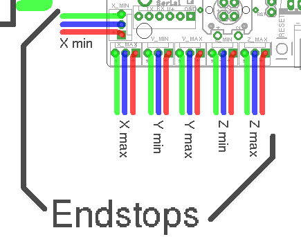
You want to connect the Signal (green in the schematic) and Ground (blue in the schematic) pins for the end-stop on the Smoothieboard, to the C and NC connection points on the end-stop.
For each endstop, we connect C to Signal and NC to Ground because this means the digital input pin (endstop connector) will be connected to Ground in its normal state and cut from Ground when the button is pressed. This approach is less prone to noise than the reverse. See here for more information.
Another positive effect of this approach is, that if a wire breaks for some reason you get the same signal as if the endstop is pressed. That makes sure that even with a damaged wire you are not able to overrun the endstop.
Make absolutely sure that you do not connect VCC (red) and GND (blue) to a mechanical (microswitch) endstop! Depending on your wiring this may fry your Smoothieboard instantly or when the switch gets pressed. There is certain wiring where this won't happen when you switch the signal between VCC and GND, but if you're not careful enough you will damage your board.
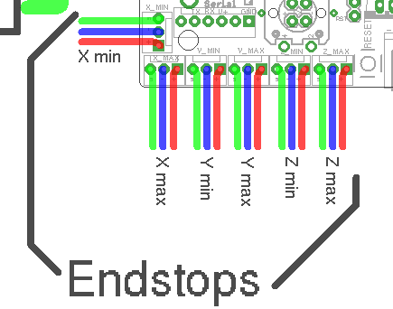
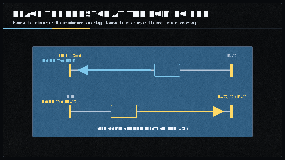
For a machine which homes at the minimum end, connect X to X min, Y to Y min, and Z to Z min. If an axis homes at the other end, use its max connector and configure home_to_max instead.
Pin names
On a Smoothieboard V1, the six endstop inputs map like this:
| Endstop | X MIN | X MAX | Y MIN | Y MAX | Z MIN | Z MAX |
|---|---|---|---|---|---|---|
| Config value | alpha_min |
alpha_max |
beta_min |
beta_max |
gamma_min |
gamma_max |
| Pin name |
See the Smoothieboard V1 pinout for the connectors themselves.
V2 uses these configuration names:
| Endstop | X MIN | X MAX | Y MIN | Y MAX | Z MIN | Z MAX |
|---|---|---|---|---|---|---|
| Config value | minx |
maxx |
miny |
maxy |
minz |
maxz |
| Processor pin | Board-specific | Board-specific | Board-specific | Board-specific | Board-specific | Board-specific |
The bundled Smoothieboard V2 configurations currently use PD0, PI1, and PI0 for X min, Y min, and Z min respectively; check the configuration supplied with your board rather than treating that set as universal.
An older version of this guide showed PG10, PG9, PG11, PG12, PG13, and PG14 as if they were the V2 equivalent of the six V1 inputs. That was not safe as a general V2 pin table. Use the Smoothieboard V2 Prime board page and STM32H7 pin-use reference for the board in front of you.
Test the endstop before moving the axis
The default configuration most probably already has everything you need: the pins are already correct and the default speeds are reasonable. Still, test the electrical input before asking the machine to move.
Reset your Smoothieboard, then connect to it using host software like Pronterface or the web interface. For this first electrical test, keep motor power off.
Use the
Depending on the firmware version, Smoothie answers in one of these forms:
X min:1 Y min:0 Z min:0
min_x:0 min_y:0 min_z:0 max_x:0 max_y:0 max_z:0
ok
The first example means the X endstop is pressed, while Y and Z are not. An input configured as nc (meaning “not connected”) will not be reported.
Use a combination of this command, and manually pressing the end-stop, to determine what is going on.
- If an end-stop is read as always pressed, or never pressed, even when you press or release it, then you probably have a wiring problem. Check everything.
- If an endstop is read as pressed when it is not, and not pressed when it is, then your end-stop is inverted.
- If an input does not appear, configure its pin instead of
nc, restart the board, and repeat the test.
You can reverse a pin in the configuration file by adding or removing a ! character after the pin number. For example, if the V1 X min endstop is inverted, change:
alpha_min_endstop 1.24^
to:
alpha_min_endstop 1.24^!
See Pin Configuration for the meaning of ^, v, and !.
Configuration
Wire and test the switch with
Quick migration guide
Here is the same basic three-axis, home-to-min setup in V1 and V2 format:
V1 flat configuration:
alpha_min_endstop                            1.24^!
alpha_homing_direction                       home_to_min
alpha_min                                    0
alpha_max                                    200
alpha_max_travel                             500

beta_min_endstop                             1.26^!
beta_homing_direction                        home_to_min
beta_min                                     0
beta_max                                     200
beta_max_travel                              500

gamma_min_endstop                            1.28^!
gamma_homing_direction                       home_to_min
gamma_min                                    0
gamma_max                                    200
gamma_max_travel                             500
V2 INI configuration:
[endstops]
minx.enable = true
minx.pin = PD0^
minx.homing_direction = home_to_min
minx.homing_position = 0
minx.axis = X
minx.max_travel = 500

miny.enable = true
miny.pin = PI1^
miny.homing_direction = home_to_min
miny.homing_position = 0
miny.axis = Y
miny.max_travel = 500

minz.enable = true
minz.pin = PI0^
minz.homing_direction = home_to_min
minz.homing_position = 0
minz.axis = Z
minz.max_travel = 500
Those pins are the ones used by the bundled V2 reference configurations. Confirm them against the configuration and pinout for your exact board before copying the block.
Set home_to_max and configure the maximum input instead if the switch is at the far end of the axis. Do not enable homing on an axis which has no homing switch.
All configuration options
The large setting table has been split into the complete Endstop configuration reference. It contains every V1 and V2 setting from the original page: homing modes and order, debounce, delta and SCARA trim, all six input pins, positions, maximum travel, hard limits, fast and slow rates, and retract distances. It also contains the endstop signal diagram. Nothing in that table has been summarized away.
Use the short example above to get the ordinary case running. Open the full table when you need to change rates, retract distance, debounce, trim, a maximum switch, or a less common kinematics setup.
Homing
Once
In RepRap mode, home one axis first. For example:
G28 Z0
will home the Z axis.
And:
G28
will home all axes which have endstops enabled, which is all three in the standard V1 configuration.
If your axis moves until it hits the end-stop, stops, moves a small distance back, then goes a bit slower back to the end-stop and stops again, that end-stop is working fine.
If the axis moves a small distance in the wrong direction and stops, Smoothie most probably thinks the endstop is already pressed. Check ! on the pin.
If the axis moves and never stops, even after the end-stop is physically hit, Smoothie never sees the end-stop as pressed. Cut motor power and go back to the wiring and
If the axis moves away from the switch, correct the homing direction or the motor direction before trying again.
firmware-cnc.bin firmware is in CNC mode and uses GRBL compatibility mode by default. In that mode $H or When you home a delta that has non-zero trim values, you will find that X and Y are not 0 after homing. This is normal.
If you want X0 Y0 after homing, set
true. This moves the effector to 0,0 after homing and applying the trim. Make absolutely sure the carriages can come off the switches and make that move safely; otherwise it may crash into your endstops.
Limit switches
Endstops may also act as limit switches. During normal operation, triggering any enabled limit switch halts the system and stops all operations. Smoothie sends !! to the host so it stops sending more data; recent development versions of OctoPrint and Pronterface support this.
Sending $X, sending
While a limit switch is still triggered, the limits are disabled so that you can jog off it. This is far from perfect but it is a compromise: otherwise the only option would be to push the axis off the switch by hand. Jog slowly and be ready to cut motor power, because a move in the wrong direction can crash the machine into the limit.
To enable hard limits, use the following options. They are disabled by default.
alpha_limit_enable   true   # enable X min and max limit switches
beta_limit_enable    true   # enable Y min and max limit switches
gamma_limit_enable   true   # enable Z min and max limit switches
In V1, enabling an axis enables both its minimum and maximum inputs as limits. Set an absent input pin to nc to disable that end.
[endstops]
minx.limit_enable = true
miny.limit_enable = true
minz.limit_enable = true
V2 enables the limit role per input. Enable maxx.limit_enable, maxy.limit_enable, or maxz.limit_enable only if that maximum input is configured and physically present.
After homing, the axis is usually left pressing the switch. When limits are enabled, Smoothie backs off by
The downside is that if you home to 0 and the switch is still triggered at 0, moving to 0,0 will fire the limit again. Set a homing offset such as M206 X-5 Y-5, using enough distance to come off the switch. An alternative is to set the minimum or maximum X and Y coordinates to -5 instead of 0. That way you can home and still safely go to 0 without triggering another limit event.
You can also enable software endstops and configure them to refuse moves beyond the work area. This makes the recovery compromise a bit safer, but it only helps after the machine has homed and knows where it is.
Some boards have only three connectors, which is not enough for one switch at each end of all three axes. You can still put two switches on one connector:
- Connect two normally-closed switches in series
- Or connect two normally-open switches in parallel
Soft endstops
Soft(ware) endstops allow the board to refuse any command that would put the tool outside the bounds of the work area.
This only functions once the machine has been homed; until then it cannot know where it is. After homing, send
soft_endstop.enable   true   # enable soft endstops
soft_endstop.xmin     1      # minimum X position
soft_endstop.xmax     999    # maximum X position
soft_endstop.ymin     1      # minimum Y position
soft_endstop.ymax     499    # maximum Y position
soft_endstop.zmin     1      # minimum Z position
soft_endstop.zmax     199    # maximum Z position
soft_endstop.halt     true   # halt instead of ignoring an out-of-bounds command
The old page contained a V2 [soft_endstop] block obtained by translating the V1 names. The bundled V2 configurations do not contain that block, so it is not reproduced here as working configuration. Do not guess configuration syntax on a machine that can damage itself: use a V2 firmware version which documents software limits, or verify the feature against the exact firmware you are running.
It is highly recommended that you always enable HALT when a soft endstop is hit. The “ignore command” option is VERY dangerous: later commands inside the limits continue from a position the host did not expect, which can cause untold damage.
Usage example with home offsets
Here is a common sequence you may use to set bed height. This need not be repeated unless the bed changes.
; Home
G28
; move to 5mm above bed
G0 Z5
; then manually jog down until nozzle is on bed or just traps a sheet of thin paper
; sets the Z homing offset based on current position
M306 Z0
G28
G0 Z0
; check nozzle still captures thin sheet of paper
M500
; saves the results in EEPROM equivalent
See Gamma max for the complete Z-height procedure.
Changing the origin
The homing position, or origin, is the 0,0 position relative to which the machine moves.
On a delta, the homing position is automatically the center of the bed.
On a Cartesian machine, however, it is the point at which the end-stops are hit, generally a corner of the machine. You might want to have a different origin point though.
For example, if your X axis homes to the maximum endstop, and that endstop is 200 mm away from the machine origin, tell Smoothie where that switch is with:
alpha_max 200
If X homes to the minimum endstop, the work area is 200 mm wide, and you want the origin at the center, use:
alpha_min -100
By default, the machine homes and sets the current position as configured, but does not move to 0,0 afterward. Set move_to_origin_after_home to true if you want that move, once you have made sure the path is clear.
Powered endstops wiring
Mechanical endstops are simple switches: they let a signal pass through, or not. They have no intelligence of their own.
There are more sophisticated endstops, for example Hall-effect or optical sensors. These are powered endstops. Besides Signal and Ground, they need a power supply—but not necessarily 5 V. Check the data sheet for the required supply voltage, the output voltage, and the output type before connecting anything.
Different powered endstops behave differently. Some pull Signal to Ground when triggered; others produce a high voltage. Some have open-collector outputs and need a pull-up. To know exactly what your endstop does, see its documentation. In particular, do not assume that an inductive or capacitive sensor powered at 24 V produces a voltage which is safe for a Smoothieboard input.
If ! just as you would for a mechanical switch.
Some powered endstops need the internal pull-up removed. On V1 X min, change:
alpha_min_endstop 1.24^
to:
alpha_min_endstop 1.24
If the input needs a pull-down, use:
alpha_min_endstop 1.24v
In some very rare cases, the endstop reading circuit on the Smoothieboard will not suit the sensor. Use a compatible free GPIO only after checking the pinout and pin configuration rules.
Types of endstops
The sensor comparison has been split into the complete Endstop and probe sensor types table. It keeps all eight original rows—mechanical, optical, Hall effect, inductive, capacitive, force-sensitive resistor, IR probe, and BLTouch—with their uses, pros, cons, ratings, advice, and the Reprap Z-probe link.
The short version is that mechanical switches are the simplest, cheapest, and most reliable option. Don’t use anything else unless you have a very good reason to. Just getting a fancier sensor because it feels cool to do so is most likely going to bite you in the back quickly. For a retractable Z probe, BLTouch is essentially a servo-mounted mechanical switch and is also a good option.
Going further
Smoothie is Open Source, so if you are curious how the module works, you can simply look at the V1 endstop code.
Useful pages to keep nearby:
- Complete Endstop configuration reference
- Endstop and probe sensor types
- G28 command reference
- Smoothieboard V1 pinout
- Smoothieboard V2 Prime board page
- STM32H7 pin-use reference
- Z probe setup
General video about mechanical endstops
If you would rather see a mechanical endstop explained, this video may help: