Using Panel controllers with Smoothieboard
« Panels » are a combination of a LCD screen, and some sort of input method ( encoder wheel, or buttons ).
They are used to control your machine without having to use a host computer and a USB or Ethernet connection.
To use a Panel, you need to wire it to your Smoothieboard, and to set it up in your configuration file.
This page describes the wiring and configuration for the currently supported panel types.
Supported Panels
The following panels are currently supported by Smoothie :
- ReprapDiscount GLCD
- Universal Panel Adapter
- Viki2 and Miniviki2, from panucatt
- SSD1306 based OLED displays
Supported SPI chips:- ST7565, ST7920, SSD1306
universal_adapter driver : - old Viki lcd I2C - Most reprap style parallel LCD - Parallel - Panelolu2 probably works but not tested - I2C
Configuration
All configuration options
Here are all the configuration options available for the Panel module :
| V1 Setting | V2 Setting | Description |
|---|---|---|
|
Enables the panel interface module. Panels provide a screen, an encoder wheel and/or a set of buttons, used to control your machine without requiring a computer connection. When enabled, the panel module initializes the LCD driver, configures input devices, and registers for system events to display machine status and accept user input. If disabled, the panel module is completely removed from memory. |
||
|
Specifies the type of panel connected to the Smoothieboard. Each panel has specific interface and driver requirements, so the correct panel type must be set. The value determines which panel driver is loaded and initialized. Different panels have different pin requirements, button configurations, and display capabilities. |
||
|
Selects which SPI channel to use for panel communication. The Smoothieboard has two SPI channels with different pin assignments. Channel selection affects which physical pins are used for MOSI, MISO, and SCLK signals. Most panels use channel 0 by default. |
||
|
Specifies the CS (Chip Select) pin used to select the panel device on the SPI bus. CS allows multiple devices to share the same SPI port by activating only the selected device. When CS is low (active), the panel responds to SPI commands; when high (inactive), the panel ignores SPI traffic. |
||
|
|
||
|
|
||
|
|
||
|
Number of lines to offset the menu lines by on screen. On some panels, this value must be set to Adjust if menu items don't align properly on your display. |
||
|
A pin for the encoder wheel. Encoders have two pins, A and B; set this to The |
||
|
B pin for the encoder wheel. Encoders have two pins, A and B; set this to The |
||
|
|
||
|
Pin for the click ("enter" or "select") button, typically pressed to select menu items, confirm actions, and accept value changes. The |
||
|
Pin for the back ("escape" or "cancel") button, which returns to the previous menu level or cancels the current operation. On Viki2 panels, this pin may be used for either back button or pause button functionality. |
||
|
|
||
|
|
||
|
|
||
|
|
||
|
Pin for the buzzer, which provides audio feedback for button presses and alerts. Some panels have a built-in buzzer that requires this pin to be configured. |
||
|
Pin for the red LED on Viki2 panels, which typically indicates heating status or errors. Only available on Viki2 and similar panels with status LEDs. |
||
|
Pin for the blue LED on Viki2 panels, which typically indicates cooling or idle status. Only available on Viki2 and similar panels with status LEDs. |
||
|
If using a Viki or SSD1306, this pin drives the C/D (Command/Data) pin on the display. It distinguishes between command and data bytes in the SPI communication. |
||
|
If using an SSD1306, this pin is sometimes required and connects to the reset pin on the display. The reset pin is used to initialize the display controller. |
||
|
If using the The universal adapter uses this pin for daisy-chaining multiple devices. |
||
|
X (Alpha) axis jogging feedrate in millimeters/minute, used when jogging from the panel screen. Adjust based on your machine's capabilities and desired jogging speed. |
||
|
Y (Beta) axis jogging feedrate in millimeters/minute, used when jogging from the panel screen. Adjust based on your machine's capabilities and desired jogging speed. |
||
|
Z (Gamma) axis jogging feedrate in millimeters/minute, used when jogging from the panel screen. Typically slower than XY jogging, for precision and safety. |
||
|
Temperature to set the hotend to when using the pre-heating menu item on the panel — a quick-access, one-button preset for heating to a commonly used temperature. Set this to match your most commonly used filament type. |
||
|
Temperature to set the bed to when using the pre-heating menu item on the panel — a quick-access, one-button preset for heating to a commonly used temperature. Set this to match your most commonly used filament type. |
||
|
Set to Enables an additional SD card interface beyond the onboard SD slot. |
||
|
Set the SPI channel the external SD card is on. This must match the SPI channel used by the panel if they share the same SPI port, or can be a different channel if separate. |
||
|
Set the CS (Chip Select) pin for the external SD card. This allows multiple devices to share the same SPI port, as long as each has a unique CS pin. |
||
|
SD card detect signal pin, which detects when an SD card is inserted or removed. Set to |
||
|
|
||
|
When set to You can create any number of custom entries, as long as each has a different name. |
||
|
The name displayed in the panel's menus — what the user sees when browsing the menu. Underscores ( |
||
|
The command executed when the menu entry is selected and clicked. The |
Custom menu entries
Menu entries can be added from the config file for simple commands, for instance the following adds a Power on and Power off menu entry.
Note that _ will be converted to a space when displayed in the Menu. Commands can be seperated with a |. If you want to add a menu entry that probes your z-axis you will have to use a command like
V1 Configuration:
custom_menu.power_on.enable              true              #
custom_menu.power_on.name                Power_on          #
custom_menu.power_on.command             M80               #

custom_menu.power_off.enable             true              #
custom_menu.power_off.name               Power_off         #
custom_menu.power_off.command            M81               #
Another example for filament change:
custom_menu.filament_change_c.enable               true                                                   #
custom_menu.filament_change_c.name                 Change Filament                                        #
custom_menu.filament_change_c.command              G91|G1_Z0.6_F12000|G90|G1_X0_Y0|G91|G1_Z-0.6|G90|M25   #

custom_menu.filament_change_r.enable               true              #
custom_menu.filament_change_r.name                 Resume            #
custom_menu.filament_change_r.command              M24               #
V2 Configuration:
[custom_menu.power_on]
enable = true
name = Power_on
command = M80

[custom_menu.power_off]
enable = true
name = Power_off
command = M81
Another example for filament change:
[custom_menu.filament_change_c]
enable = true
name = Change Filament
command = G91|G1_Z0.6_F12000|G90|G1_X0_Y0|G91|G1_Z-0.6|G90|M25

[custom_menu.filament_change_r]
enable = true
name = Resume
command = M24
External SD card setup
For the RRD GLCD it CANNOT share the same SPI as the LCD so it must be hooked up to the onboard sdcard SPI and use a spare pin for the sdcs. Also note that an external SDcard sharing the SPI port with the onboard/internal sdcard must be ejected before rebooting as the bootloader does not like the external card. NOTE Smoothie will not boot if the external sdcard is inserted in the RRD LCD sdcard slot at boot time, it must be inserted after it has booted.
If the lcd panel has an sdcard reader it can be enabled with the following config:
# setup for external sd card on the viki2 which shares the lcd spi port with the sdcard
panel.external_sd                         true           # set to true if there is an extrernal sdcard on the panel
panel.external_sd.spi_channel             0              # set spi channel the sdcard is on
panel.external_sd.spi_cs_pin              0.27            # set spi chip select for the sdcard
panel.external_sd.sdcd_pin                0.28!^          # sd detect signal (set to nc if no sdcard detect)
# setup for external sd card on the RRD GLCD which shares the onboard sdcard SPI port
panel.external_sd                        true             # set to true if there is an extrernal sdcard on the panel
panel.external_sd.spi_channel            1                # set spi channel the sdcard is on
panel.external_sd.spi_cs_pin             0.27             # set spi chip select for the sdcard (or any spare pin)
panel.external_sd.sdcd_pin               0.28!^           # sd detect signal (set to nc if no sdcard detect) (or any spare pin)
Using the spare button as a Kill switch
The button on the glcd and Viki2 can be wired as a Kill button by following This guide. In that case the
should be commented out.
A RRD GLCD showing Smoothie's "watch" screen
Reprap Discount GLCD
The Reprapdiscount GLCD is a black and white graphical display with an encoder control button that allows you to control your Smoothieboard.
It is one of the most popular options for panel controllers.
If you are using the onboard 5V regulator to step down from 12/24V, check the current draw required for your panel - depending on the color/backlight on your GLCD, it may require >250 mA for the backlight.
The normal recommended 5V regulator will not supply enough current for those panels - if the panel powers up, it will have very low contrast.
Use Recom part
R-78E5.0-**1.0** instead - it will supply 1 amp (vs 0.5 amps for the normally recommended regulator).It is available at Digikey, and likely at other major electronics component sites.
See Voltage Regulator.
As an alternative to replacing the R-78E5.0 part on the Smoothieboard, solder a 5V 0.5 amp or 1 amp regulator to the adaptor card in the location marked. Ordinary 7805 regulators will work in that role. See 78xx
There is an adapter board to easily connect a ReprapDiscount GLCD to a Smoothieboard with flat cable, however note this is entirely optional.
You can find information about it at the RRDGLCDAdapter page.
It's sources are available on github.
Note that you may have to solder physical pins to the board for pins
If you buy one of them, you need to modify your adapter board, by removing the sockets of the 10-pin connectors and rotating them 180 degrees each.
This means you won't be able to use SPI thermocouples and the RRD GLCD together on the same board, unfortunately.
Manual wiring
On the back of the GLCD EXP1 is to left and EXP2 is to right, pin 1 is bottom left, pin 2 is top left etc. 5v is EXP1 pin 10, Gnd is EXP1 pin 9
V1 Configuration:
# config settings
panel.enable                          true              # set to true to enable the panel code
panel.lcd                             reprap_discount_glcd     # set type of panel
panel.spi_channel                     0                 # spi channel to use  ; GLCD EXP1 Pins 3,5 (MOSI, SCLK)
panel.spi_cs_pin                      0.16              # spi chip select     ; GLCD EXP1 Pin 4
panel.encoder_a_pin                   3.25!^            # encoder pin         ; GLCD EXP2 Pin 3
panel.encoder_b_pin                   3.26!^            # encoder pin         ; GLCD EXP2 Pin 5
panel.click_button_pin                1.30!^            # click button        ; GLCD EXP1 Pin 2
panel.buzz_pin                        1.31              # pin for buzzer      ; GLCD EXP1 Pin 1
panel.back_button_pin                 2.11!^            # 2.11 menu back      ; GLCD EXP2 Pin 8
# setup for external sd card on the GLCD which uses the onboard sdcard SPI port
panel.external_sd                     true              # set to true if there is an extrernal sdcard on the panel
panel.external_sd.spi_channel         1                 # set spi channel the sdcard is on
panel.external_sd.spi_cs_pin          0.28              # set spi chip select for the sdcard (or any spare pin)
panel.external_sd.sdcd_pin            0.27!^            # sd detect signal (set to nc if no sdcard detect) (or any spare pin)
V2 Configuration:
[panel]
enable = true
lcd = reprap_discount_glcd
spi_channel = 0
spi_cs_pin = PG7
encoder_a_pin = PJ3
encoder_b_pin = PJ4
click_button_pin = PJ5
buzz_pin = PJ6
back_button_pin = PJ7

[panel.external_sd]
enable = true
spi_channel = 1
spi_cs_pin = PC1
sdcd_pin = PC0
Note: V2 uses STM32 pin naming (e.g., PG7 instead of 0.16).
You can find a list of pins on the Smoothieboard to connect to the panel here and here.


Be aware that RRD does not follow proper conventions for pin numbering. The pin 1 indicator on the ribbon is actually pin 10 in the RRD schematic. The image above is numbered according to the RRD inset schematics.
RRD GLCD to Azteeg X5 Mini v1.1 interface board
This interface board is simple to install, eliminates custom cables, frustration, and wire mess.
It is compatible with Azteeg X5 Mini v1.1 motion controller and is available from www.UltiBots.com. Source files are on our GitHub.
GLCD to Azteeg X5 Mini Wiring Harness
Azteeg X5 Mini to RRD GLCD wiring harness
This wiring harness uses three 2x10, one 1x2 .100” crimp housings and one heat shrinked female pin to connect the RRD GLCD to an Azteeg X5 Mini.
Note: This information is compatible with Azteeg X5 Mini v1.0 motion controllers.
Viki2 from panucatt.com
Viki2 wires to an Azteeg X5 mini with a flat cable as it has 1:1 pin mapping. The ConfigSample for the Azteeg mini has the config settings required, just uncomment them,
The config for Azteeg X5 is different to smoothieboard and is shown in the file here.
Here is an example config for a 4 driver smoothieboard
NOTE a 5 driver does not have enough free pins to use all the features
# For 4 driver Smoothie board NOT azteeg X5 or 5 driver smoothie
panel.enable                                 true              # set to true to enable the panel code
panel.lcd                                    viki2             # set type of panel
panel.spi_channel                            0                 # set spi channel to use P0_18,P0_15 MOSI,SCLK
panel.spi_cs_pin                             0.16              # set spi chip select
panel.encoder_a_pin                          3.25!^            # encoder pin
panel.encoder_b_pin                          3.26!^            # encoder pin
panel.click_button_pin                       1.30!^            # click button
panel.a0_pin                                 2.11              # st7565 needs an a0
#panel.contrast                              8                 # some panels need contrast set, this is for viki2
#panel.encoder_resolution                    4                 # number of clicks to move 1 item
panel.buzz_pin                               1.31              # pin for buzzer
panel.red_led_pin                            1.22              # pin for red led on viki2 (5 driver can't use this)
panel.blue_led_pin                           1.23              # pin for blue led on viki2 (5 driver can't use this)
#panel.back_button_pin                        1.30!^           # optionally using the red buttin as a back button
# setup for external sd card on the viki2
panel.external_sd                            true              # set to true if there is an extrernal sdcard on the panel
panel.external_sd.spi_channel                0                 # set spi channel the sdcard is on
panel.external_sd.spi_cs_pin                 2.8               # set spi chip select for the sdcard (NOTE 5 drvier can't use this)
panel.external_sd.sdcd_pin                   2.13!^            # sd detect signal (set to nc if no sdcard detect) (NOTE 5 drvier can't use this)
Using the suggested firmware above the wiring for the Viki 2.0 on a 4 driver smoothieboard is as follows:
SDCD to P0.27
BTN to P1.30
SDCS to P2.8
LCS to P0.16
SCK to P0.15
GND to 5v power supply's ground or a ground pin on the smoothieboard
ENCB to P3.26
ENCA to P3.25
MISO to P0.17
A0 to P2.11
MOSI to P0.18
=Vin to 5v power supply

BTN to None, Viki 2.0 has 2 Blue BTN wires that do the same thing
Buzzer to P1.31
Blue-LED to P1.23
Red-LED to P1.22
This wiring uses this smoothie pin map and this Viki 2.0 wiring guide.
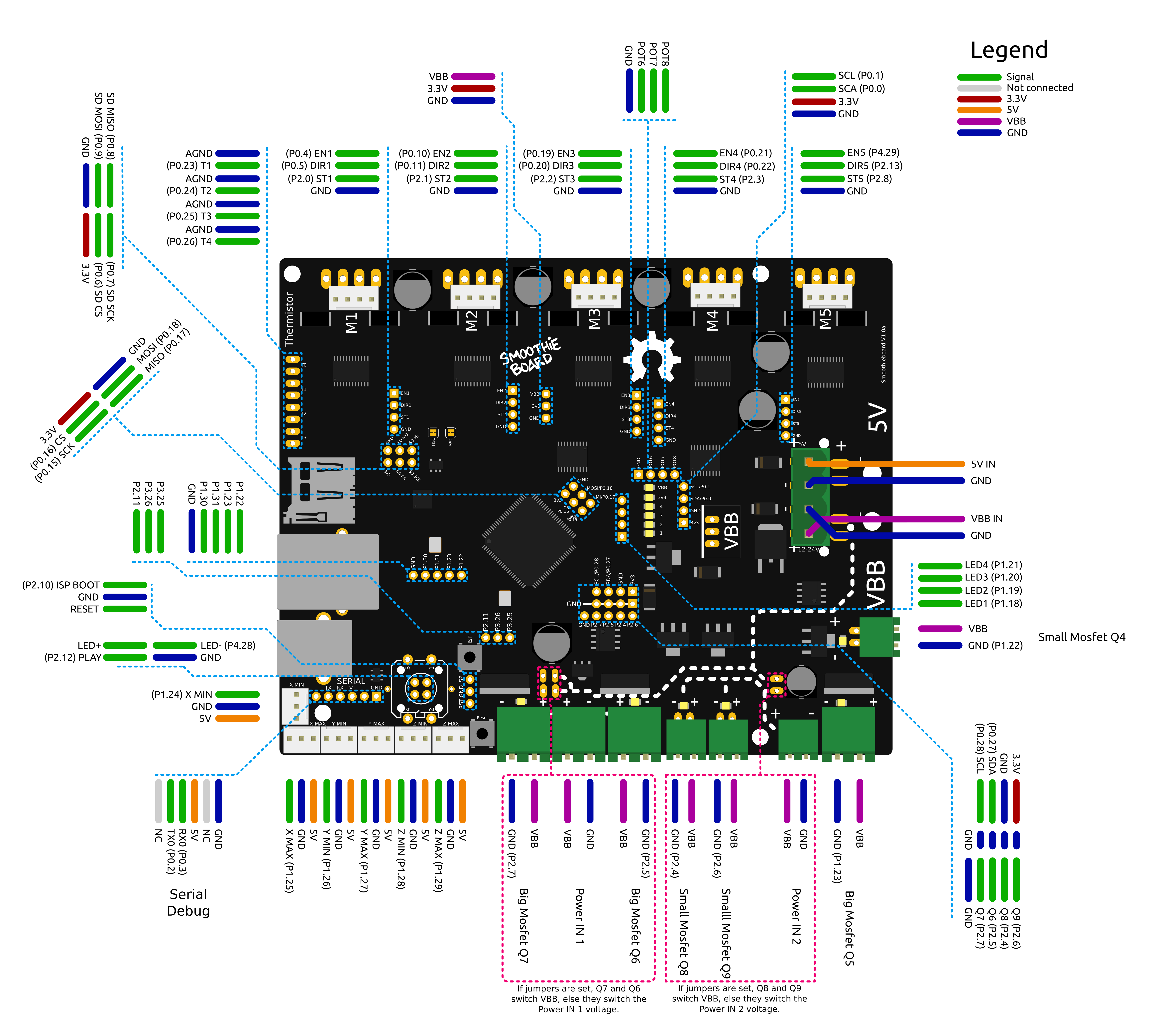
5 driver smoothieboard, disables buzzer and uses red led instead
# For 5 driver Smoothie board NOT azteeg X5
panel.enable                                 true              # set to true to enable the panel code
panel.lcd                                    viki2             # set type of panel
panel.spi_channel                            0                 # set spi channel to use P0_18,P0_15 MOSI,SCLK
panel.spi_cs_pin                             0.16              # set spi chip select
panel.encoder_a_pin                          3.25!^            # encoder pin
panel.encoder_b_pin                          3.26!^            # encoder pin
panel.click_button_pin                       1.30!^            # click button
panel.a0_pin                                 2.11              # st7565 needs an a0
#panel.contrast                              8                 # some panels need contrast set, this is for viki2
#panel.encoder_resolution                    4                 # number of clicks to move 1 item
#panel.buzz_pin                              1.31              # pin for buzzer (use red led OR buzzer not both)
panel.red_led_pin                            1.31              # pin for red led on viki2
#panel.blue_led_pin                          1.23              # pin for blue led on viki2 (5 driver can't use this)
#panel.back_button_pin                       1.30!^            # optionally using the red button as a back button (NOT available on 5 driver)
# setup for external sd card on the viki2
panel.external_sd                            true              # set to true if there is an extrernal sdcard on the panel
panel.external_sd.spi_channel                0                 # set spi channel the sdcard is on
panel.external_sd.spi_cs_pin                 0.27              # set spi chip select for the sdcard
panel.external_sd.sdcd_pin                   0.28!^            # sd detect signal (set to nc if no sdcard detect)
LCD 12864 with ST 7920 driver
Works with the Reprapdiscount GLCD driver and is available for around 7¬ or 10$. Just wire