Your guide to installing Smoothieboard in a 3D printer

Probably the machine for which Smoothie is most used, due to Smoothie’s roots in the RepRap project, 3D printers are fairly simple to Smoothiefy.
This is a step-by-step guide to connecting your board to the various components of the 3D printer, configuring everything, from the beginning to actual printing.
This guide is a community effort, and this page is a Wiki. Please don’t hesitate to edit it to fix mistakes and add information, any help is very welcome.
On a typical 3D printer setup, installing a Smoothieboard will mean you do the following things:
- Read all of the guide before you start, best way to avoid mistakes
- Install some Software to talk to your board
- Install the Windows drivers if using that OS
- Connect your board via USB and practice talking to it
- Take a look at the configuration
- Upgrade your firmware to the latest version if you feel like it
- Wire your power supply and provide it with power
- Wire the power supply to Smoothieboard’s motor and mosfet power inputs
- Connect motors to the stepper motor driver outputs
- Edit your configuration to match your motors
- Test the motors, and admire your accomplishment for hours
- Connect Endstops to the endstop inputs
- Edit your configuration to match your endstops
- Test your endstops by homing the machine
- Connect your hotend and heated bed’s thermistors to the thermistor inputs
- Edit your configuration to match your thermistors
- Test that they read temperature correctly, admire a beautiful temperature graph
- Connect your hotend and heated bed’s heaters to the mosfet outputs
- Edit your configuration to tell Smoothie what to heat, with what mosfet and how
- Test that you can correctly control temperature on all heaters, carefully
- Connect, configure and test any fans you may have
- Connect, configure and test any probes you may have
- Setup calibration or leveling if relevant
- Configure your slicing software and slice a 3D file into a G-code file
- Use your host software to send your new G-code file to the Smoothieboard
- Watch as the machine prints using your new Smoothieboard system
- Be happy
This guide will walk through everything you need to accomplish to successfully perform these steps.
At the end of this guide, you should have a fully working machine.
Translations
Some users have hand-translated this page. Note that this translated version is by definition never going to be up-to-date. Use it to help you understand in general, but any specific information should be taken from the original version, especially before asking the community for help.
Unboxing
Smoothieboard V1:
Your Smoothieboard comes with a micro SD card in the microSD slot.
The boards come pre-flashed with the latest firmware.
With a basic configuration file installed on the SD card, no preparation is needed before you can connect Smoothieboard to your computer and start interacting with it.
Smoothieboard V2 Prime:
Your Smoothieboard V2 Prime comes with an SD card (2-8 GB) in the SDIO slot, pre-loaded with firmware and a default configuration.
The boards come pre-flashed with the latest firmware.
With a default configuration file already installed on the SD card, you can connect your board immediately. The V2 also includes an onboard Ethernet port for network connectivity, which is the recommended communication method.
The first thing you might want to do before you start connecting your board is to look at our list of Software, and install a “host” program to talk to the board.
If you don't have a Smoothieboard but have or consider purchasing an MKS board, please make sure you read What's wrong with MKS
Connecting via USB

A good first step is to connect your board to your computer to familiarize yourself with it.
Connect a USB-B cable to the USB connector on the board, and to your computer.
A moment after connection, your computer will recognize the Smoothieboard as a USB Mass Storage Device (like a USB disk-drive or an SD card reader), showing you the files present on the SD card.
Drivers are needed for Windows 7/8, while Linux and Mac OS X directly support the device, you can find those drivers here.
Connect a USB-C cable to the USB connector on the board, and to your computer.
A moment after connection, your computer will recognize the Smoothieboard V2 as a USB Mass Storage Device (like a USB disk-drive or an SD card reader), showing you the files present on the SD card.
USB drivers are typically not needed on Linux, Mac OS X, or modern Windows systems. The SDIO SD card interface provides much faster transfer rates (10-25 MB/s) compared to USB Mass Storage.
This allows you to add, copy, edit, or delete any file you’d like.
Already present on the SD card is a configuration file.
This file is named “config” and contains all of the configuration options for your board in a flat text format.
The file is read when you start or reset your board.
You edit the configuration simply by editing this file in a Text Editor, saving it, and resetting the board.
This file uses INI-style sections (e.g., [actuator], [motion control]) with hierarchical settings.
The file is read when you start or reset your board.
You edit the configuration by editing this file in a Text Editor, saving it, and resetting the board. V2 configuration is structured differently from V1, so refer to the configuration guide for proper formatting.
No need to recompile or flash the board.
It can also be used to store and play G-Code files, see Player.
USB Mass Storage is not the only thing you get when you connect the board.
The board also exposes a USB CDC Serial interface, allowing you to send G-Code and receive answers.
(There is also a DFU interface for flashing firmwares but that’s mostly for developers).
The CDC (Serial) interface is the interface host programs like Pronterface use to allow you to interact with your machine.
If you are already familiar with it, you can try connecting right now and get an answer from the board.
If not, we explain it all later in this guide.
Connecting via the network

V1 Network (Optional):
The Smoothieboard V1 can optionally be connected to an Ethernet network via USB-to-Ethernet adapter or external network expansion.
This allows you to access a web interface the board can serve, and control the machine via your browser.
It also allows you to connect software that supports it (like Pronterface and Visicut) via the network.
Network connectivity is optional and disabled by default, but is easy to enable and configure if you have the appropriate hardware.
V2 Network (Built-in):
The Smoothieboard V2 Prime includes an onboard Ethernet port (RJ45) with integrated PHY, allowing direct connection to your local Ethernet network via standard network cable.
This allows you to access a web interface the board serves, and control the machine via your browser.
It also allows you to connect software that supports it (like Pronterface and Visicut) to your Smoothieboard via the network.
Network is disabled by default but is very easy to enable and configure. It is the recommended primary method of communicating with your V2 Smoothieboard.
You can find all the information you need about using the network interface here: Network interface
Updating your firmware

Before starting, a very good idea is to ensure you have the latest firmware version.
V1 Firmware Update (SD Card Method):
- Download the latest
firmware.binfile - Copy it onto the SD card
- Reset the Smoothieboard
The new firmware will “flash” (you will see the LEDs on the board do a little “dance”), and you will then have the latest version.
This is particularly useful if you ever need to ask for help, as people helping you will be assuming you have the latest version.
You can find the file, and information on how to flash it, at Flashing Smoothie Firmware.
V2 Firmware Update (Multiple Methods):
Method 1: SD Card (Recommended for first update):
- Download the latest
firmware.binfile - Copy it onto the SD card
- Reset the Smoothieboard V2
The new firmware will “flash” (you will see the LEDs on the board do a little “dance”), and you will then have the latest version.
Method 2: Network Update (requires Ethernet): Once you have network configured, you can update directly via the command:
update http://example.com/firmware.bin
This is particularly useful if you ever need to ask for help, as people helping you will be assuming you have the latest version.
You can find the file, and information on how to flash it, at Flashing Smoothie Firmware.
Migrating to Smoothie

If you are migrating from another firmware, here are guides to help you understand how some values from your old firmware match the values in your new Smoothie system.
Smoothie uses different configuration parameters and approaches than other common CNC/3D printer firmwares. These guides will help you translate your existing settings.
Migration Guides
Choose the guide that matches your current firmware:
- Moving from Marlin to Smoothie - For users coming from Marlin (common in 3D printers)
- Moving from GRBL to Smoothie - For users coming from GRBL (common in CNC mills and laser cutters)
For detailed information about configuration format differences between V1 and V2, choosing the right version, and common migration pitfalls to avoid, see the Migration Details page.
Safety Warnings
Before you start wiring your machine’s elements to the board, there are several things you need to keep in mind and be careful about during all of the assembly.
Make sure you read this. Seriously. Not kidding. Do it. It’s important.
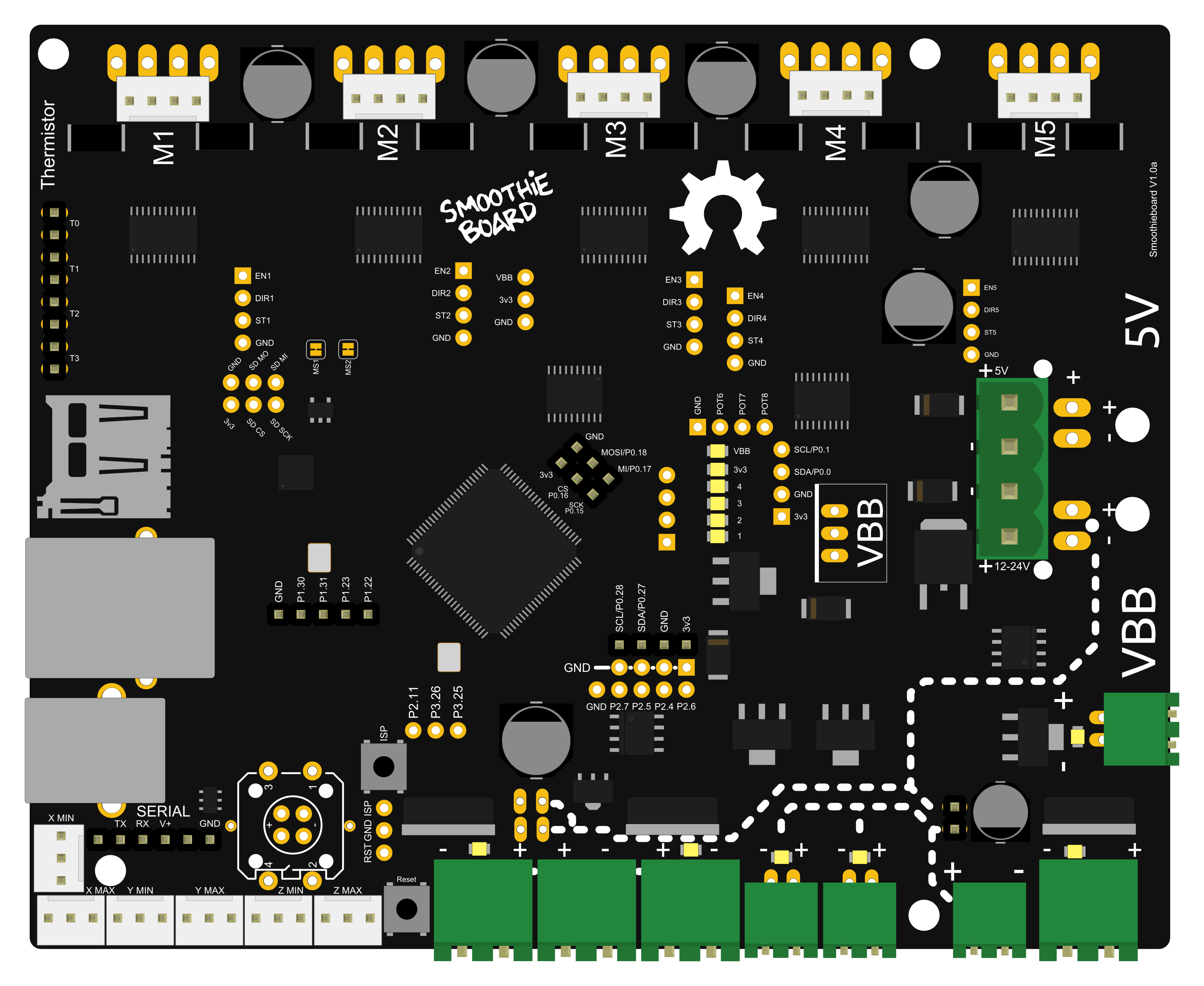
Polarity

Note the inversion between the 5mm and 3.5mm connectors
Always make sure the polarity is correct when wiring in power inputs (coming from the Power Supply). Reversed polarity can damage or destroy all or part of your board.
Polarity is indicated on the board itself by the + and - signs. Double check.
On older versions of the board, markings are partially hidden by the connector, making it confusing. Rely on only the diagrams.
How to check polarity: Attach your multimeter probes to the two wires of your power source respectively. If the voltmeter reading is positive it implies that the red probe is connected to the positive wire (+) and the black probe to the negative wire (-).
The main (labeled VBB) power input has a reverse polarity protection, however, it will not hold forever. As soon as you notice something is wrong, turn the power supply off and check again.
Disconnecting Stepper Motors
Never disconnect or connect stepper motors from the stepper motor drivers while the board is powered (i.e., when the Power Supply is turned on).
The drivers have very good protection against most possible problems and are very hard to destroy accidentally. But it is possible.
Preventing Shorts
Be careful that nothing metallic ever touches the board while it is powered on. Falling screwdrivers, nuts and bolts can cause shorts and destroy the board.
- Check the board before powering it on
- Do not press the reset button with anything metallic, as you could slip and cause a short
- Use a plastic screwdriver or the like
Using the Right Connector
Always check the schematic before connecting power sources (coming from the Power Supply) to the board. Connected to the wrong connector can destroy components.
A common example of this problem is plugging a power input cable into the connector for an output, or plugging the limit switches in backwards.
Crimping Quality
Make absolutely sure of your connections using crimps or screw terminals, from wires to any type of connector, are very careful and well done.
Connections (to the stepper motors for example) lost while the machine is running can destroy your board.
VBB Power Input Markings
In the case of the VBB power input, be careful. If your board came with connectors pre-soldered, the 5mm connector is present, and the polarity of that connector is that of the large traces in the wiring diagram to the right (red is +, blue is -).
On some boards, the marking on the boards may be hidden by the connector itself, so for VBB, do not rely on the markings on the board, but on the diagrams on this page.
However, if you did not get your connectors soldered, and want to solder a 3.5mm connector instead of a 5mm connector, also note that the polarity is the opposite.
USB vs Ethernet
USB can, in some setups, be subject to interference, which causes disconnections, and can ruin your work. This is very hard to prevent if it happens even in normal conditions.
Ethernet, on the other hand, does not have this problem: save yourself the trouble, and use Ethernet right away. It's very nice. See Network for information on how to set it up.
How to Destroy Your Board (Don’t Do These Things)
If you receive a bad board, you will get a replacement. But if you destroy your own board, your only options will be to fix it yourself (which can be quite difficult), or get a new one.
This is why it is very important you make sure you do not destroy your own board. Smoothieboard is reasonably protected, but there are still things that will destroy it.
The general idea is: if a part of the board gets too much power, it will get destroyed.
Common mistakes that cause board destruction:
- Plugging 12-24v (motor power) into anything you are not supposed to. Like the 5V line, or an end-stop or thermistor input for example. Problems with the 5V or 3.3V power are not as much of a problem as the board is 5V-tolerant, so wrong connections and shorts should be okay as long as they do not last too long.
- Shorting 12-24v to anything else, which is essentially the same as plugging it into a place you are not supposed to (see above). This can happen by dropping a metal object onto the board, bad soldering, loose wires, un-protected wires, etc ...
- Using an inductive load (like a motor, fan or solenoid) on a MOSFET, without a diode across (see Fan documentation).
The general idea here is: always make sure everything is clean, and double-check everything before turning the power on. You can not learn by making mistakes here, as mistakes will likely cost you your board.
Electrostatic discharge can also destroy your board: make sure you properly ground everything.
Heater Safety
If your machine contains any heating element and uses the temperature control module to control it, please make sure you read the section about implementing all safety measures here, and implement as many as you can.
Fires will kill you if you don't.
Grounding
Make sure your machine's case and electronics are properly grounded, also make sure your location's electrical installation's grounding is correctly done.
Grounding Resources:
Environmental Hazards
It's not just the machine itself that can be dangerous:
Laser Cutters: The machine vents large quantities of toxic smoke and gas, make sure it is very well evacuated to a place where no-one is breathing them
CNC Mills: Dusts, like wood dust for example, can be explosive if they come in contact with a flame, be careful and take measures to limit dust in the air
3D Printers: The acetone used to clean things is very flammable, and the sprays used to increase bed adherence are explosive, store them adequately and be careful when using them
Confined Spaces: You are even more in danger if you are using your machine in a confined space, always be on the watch for safety issues.
Further Reading
For a good read about safety, you can refer to the RepRap Wiki documentation on the subject.
To properly understand some of the safety instructions in this documentation, basic knowledge about electricity is required. See this page for a refresher on the basics.
Summary
- Always check polarity before connecting power
- Never disconnect motors while powered
- Keep metallic objects away from powered boards
- Double-check all connections before powering on
- Ensure quality crimps and connections
- Use Ethernet instead of USB when possible
- Implement all heater safety measures
- Properly ground your machine and workspace
- Be aware of environmental hazards
- When in doubt, power off and check
Remember: Prevention is always better than repair. Take your time, double-check everything, and never skip safety steps to save time.
Logic Power Inputs

There are different ways of providing logic power to your board.
Your board needs two sorts of power to work:
- 12-24V power to turn motors, heat hotends, etc.
- 5V (or “logic”) power to power the microcontroller (the brain)
Three Ways to Provide 5V Power
There are three ways to provide 5V power to the board:
1. Via USB cable
USB cables provide 5V directly to the board.
This is the simplest method and works well for testing and setup.
2. Via voltage regulator
By soldering a voltage regulator to the board (and providing 12+24V, which the voltage regulator then turns into 5V).
This allows the board to be powered from your main power supply.
3. Direct 5V input
By providing 5V directly to the 5V power input (next to the VBB power input).
This requires a separate 5V power supply.
Simplest Solution
If you want to keep it simple, the easiest solution is just to connect your Smoothieboard to your computer via USB.
Multiple Power Supplies
Smoothieboard has diodes on-board that will simply get the power from the one with the highest voltage.
This means you can even turn one off and the other will be used without a reset.
Understanding Voltage and Current
If voltage and current are strange concepts to you, it’s probably a good idea before you continue setting up your board, that you read this introduction.
Power Consumption
The board’s logic circuits (5V line) typically consume up to 500mA current (what is standard for a USB port).
Your board needs two sorts of power to work:
- 12-24V power to turn motors, heat hotends, etc.
- 5V (or “logic”) power to power the microcontroller (the brain)
Three 5V Power Sources
Smoothieboard v2 supports three different 5V power sources, with automatic switching between them:
1. Onboard 5V Regulator (Recommended)
The board has a built-in 3A switching regulator that converts your motor power (Vmot, 12-24V) to 5V.
| Specification | Value |
|---|---|
| Output Current | 3A continuous |
| Input Source | Vmot (12-24V) |
| Efficiency | 85-90% (switching regulator) |
| Disable Jumper | JP16 (near OSHW logo, top side) |
This is the preferred power source for most setups. It provides enough current to power:
- The board itself (~300-500mA)
- A Raspberry Pi (~500-1500mA)
- A small touchscreen (~400-700mA)
Using the onboard regulator means you only need one power supply (12-24V) for your entire system - no separate 5V supply required!
2. USB Power
USB provides 5V directly to the board, limited to ~500mA (USB specification).
| Specification | Value |
|---|---|
| Output Current | ~500mA (USB spec limit) |
| Disable Jumper | JP15 (bottom side, near 5V input) |
This is useful for:
- Testing and initial setup
- Low-power configurations
- When Vmot is not connected
If you're connecting a Raspberry Pi to the board via USB, you may want to cut the JP15 jumper to prevent the Pi from attempting to power the board through USB (which could cause issues).
3. External 5V Input
You can provide 5V directly via the dedicated 5V input header.
| Specification | Value |
|---|---|
| Connector | 5Vin header |
| Current Capacity | Depends on your external supply (2-5A recommended) |
This is useful when you:
- Have a dedicated 5V power supply
- Need more than 3A for peripherals
- Want to keep 5V power independent from motor power
Automatic Power Source Selection
You can connect multiple 5V sources simultaneously! The board automatically selects the best source.
Smoothieboard v2 uses ideal diode ORing for automatic power source selection:
- Automatic switching: The board selects the source with the highest voltage
- Backflow prevention: Power cannot flow backward between sources
- Minimal voltage drop: Only ~tens of mV loss (vs ~600mV with standard diodes on v1)
- No manual switching: Connect everything, and it just works
Typical priority order:
- Onboard regulator (if Vmot present)
- External 5V input
- USB power (if jumpers intact)
This means you can turn off one power source and the board will seamlessly switch to another without resetting!
Power Status LEDs
Smoothieboard v2 has several LEDs to help you monitor power status:
| LED | Indicates |
|---|---|
| Vmot LED | Motor power present (12-24V) |
| Vfet LED | MOSFET power present (12-24V) |
| 3.3V LED | Logic power present (board is on) |
| MSD LED | Mass Storage Device mode active |
| Debug LEDs | 4× programmable status LEDs |
Disabling Power Sources with Jumpers
You can physically disable individual power sources by cutting jumpers:
- JP15: Cut to disable USB 5V input (useful when connecting Raspberry Pi via USB)
- JP16: Cut to disable onboard 5V regulator (if using external 5V supply exclusively)
Most users should leave all jumpers intact. Only cut them if you have a specific reason (like preventing USB backfeeding from a Raspberry Pi).
Understanding Voltage and Current
If voltage and current are strange concepts to you, it’s probably a good idea before you continue setting up your board, that you read this introduction.
Power Budget Example
Here’s a typical power budget for a 3D printer with Raspberry Pi:
| Component | Current @ 5V |
|---|---|
| Board logic | ~300-500mA |
| Raspberry Pi 3 | ~500-1500mA |
| 7” touchscreen | ~400-700mA |
| Total | ~1.2-2.7A |
The onboard 3A regulator handles this comfortably with headroom to spare!

Be careful, mains voltage is dangerous
Main Power Input
Without power, your board cannot do much.
The board uses power to operate the control logic, move stepper motors, power heating elements, fans, and other peripherals.
How to choose a power supply unit (PSU)
Two power supplies are required, 5.0V and ‘bulk’ power (VBB).
5.0V supply
- Voltage (V): The 5.0V supply should be regulated to 5% tolerance (4.75V to 5.25V). This supply provides power for the control logic circuitry, and should be a good quality regulated power supply (which is inexpensive). Using a cheap buck regulator from a higher voltage is not recommended, as ever exceeding 5.5V on this supply may instantly and permanently damage the control logic on your Smoothieboard.
- Current (A): The 5.0V supply should be rated to supply at least 1A continuous current (or more). Typical load is roughly 0.5A.
VBB supply
- Voltage (V): VBB can be from 12 to 24V. While most of the components on the Smoothieboard are rated up to 32V, it is not recommended or supported to use that high of a voltage. 12V PSUs are more common, and generally cheaper. However, the higher the voltage, the higher performance you can get from your stepper motors. This is the reason some designers use 24V PSUs. However, be careful that with a 24V PSU, you will need 24V fans, and will need to reduce the PWM setting for your heating elements or (preferred, and safer) use 24V heating elements.
- Current (A): The total current required is the current for each stepper motor, plus the current for every peripheral on your machine Smoothieboard will control. This depends on your machine type. On a typical 3D printer, you can safely consider 10A to be sufficient for the heated bed, and 10A or a bit less for the rest of the loads. Go for a 17 to 20A PSU if you have a heated bed. 7A to 10 is probably enough if you do not have a heated bed (or if you are setting up a CNC mill or a laser cutter). If you bought your machine as a kit, a PSU with appropriate current is most probably provided (or one is recommended). If building your machine yourself by self-sourcing, the documentation for the machine model will also most probably recommend a current rating. A power supply that is able to supply more current than is needed is not a problem. Having not enough current to drive your hot-end, heater bed, or motors is a problem.
Power Architecture Overview
Smoothieboard v2 uses a dual power architecture that separates motor power from MOSFET (heater/fan) power. This provides better current handling and more flexibility.
| Power Domain | Connector | Voltage | Purpose |
|---|---|---|---|
| Vmot | 1× XT30 | 12-24V DC | Stepper motors + 5V logic regulator |
| VFET | 2× XT30 | 12-24V DC | All MOSFET outputs (heaters, fans) |
| 5V | Built-in | 5V DC | Logic power (from Vmot regulator) |
Unlike v1, Smoothieboard v2 has a built-in 3A, 5V switching regulator. You typically only need a single 12-24V power supply for everything!
How to Choose a Power Supply Unit (PSU)
Vmot (Motor Power)
| Specification | Value |
|---|---|
| Connector | XT30 |
| Voltage Range | 12-24V DC (24V recommended) |
| Powers | Stepper motor drivers + onboard 5V regulator |
| Typical Current | 5-15A depending on motors |
- 24V is recommended for better stepper motor performance (higher top speed, less heating)
- Components are rated to 32V, but 24V maximum is supported
- The onboard 5V regulator draws from Vmot, so ensure your PSU can handle motor current + ~1A overhead
VFET (MOSFET Power)
| Specification | Value |
|---|---|
| Connectors | 2× XT30 |
| Voltage Range | 12-24V DC |
| Current per Connector | 15A continuous |
| Total Current | 30A combined |
| Powers | All heaters, fans, SSR outputs |
Why 2× XT30 instead of 1× XT60?
- Lower vertical profile (fits in enclosures better)
- 12V heated beds draw high current and need both connectors
- 24V systems often only need one connector
12V heated bed (200W): 16.7A → Requires BOTH XT30 connectors
24V heated bed (200W): 8.3A → Single XT30 sufficient
Power Budget Examples
Typical 24V 3D Printer:
| Component | Current @ 24V |
|---|---|
| 4× Stepper motors (1.5A each) | 6A |
| Heated bed (250W) | 10.4A |
| 2× Hotends (80W total) | 3.3A |
| 2× Fans (10W total) | 0.4A |
| Board logic + peripherals | ~2A equivalent |
| Total | ~22A |
Recommended PSU: 24V, 25-30A (600-720W)
Typical 12V 3D Printer:
| Component | Current @ 12V |
|---|---|
| 4× Stepper motors (1.5A each) | 6A |
| Heated bed (250W) | 20.8A |
| 2× Hotends (80W total) | 6.7A |
| 2× Fans (10W total) | 0.8A |
| Board logic + peripherals | ~4A equivalent |
| Total | ~38A |
Recommended PSU: 12V, 40-50A (480-600W)
Notice how 24V systems draw roughly half the current for the same power. This means smaller wires, less heat, and often cheaper power supplies!
5V Logic Power
The onboard 3A switching regulator provides 5V logic power automatically when Vmot is connected. See Logic Power for details on alternative 5V sources.
General Notes
Multiple-output power supplies are available. In some cases, a minimum load must be applied to the primary output before the secondary output will be regulated to within tolerances. For example, a dual 5.0V and 12V supply might regulate the 5.0V well at no-load conditions, but the 12V output may be low until power is drawn from the 5.0V supply.
EMI Filtering
Electromagnetic Interference (EMI): Digital logic and power circuitry (such as stepper motor drivers) switches currents and voltages on and off very rapidly. This produces EMI proportional to the voltage, current and rate of switching. EMI can be radiated (as radio waves) and/or conducted through the power line cord or other connections. EMI can interfere with (produce noise in or prevent proper operation of) other equipment, including sensors and motion encoder modules. To reduce these effects, an EMI filter module may be added to help reduce the conducted emissions. An EMI filter module may not strictly be needed, however it is often simpler to take protective measures from the start rather than e.g. searching for the cause of strange, intermittent behavior or coming back to failed 3D prints for months – and then put in an EMI filter module.
Fuses / Circuit Breakers
A typical US AC wall outlet provides 110V to 120V and is protected by a fuse or circuit breaker with a 15A or 20A rating. As (for example) a motor load such as a refrigerator or saw briefly draws a much higher starting current, in order to avoid ‘nuisance trips’ a 20A rating does not instantly remove power when that load is exceeded.
A VBB power supply rated (for example) 12V at 10A can provide up to 12V x 10A = 120W (Watts) of DC power. Power supplies are not 100% efficient, thus it will require 5% to 30% more than 120W of input power to produce 120W of output power. It is usually safe to assume at least 70% efficiency at full load (higher for more modern supplies), so the power supply will only need perhaps 1.5A at 120VAC input. A 1A, 5V supply will require much less than 1A at 120VAC input.
While the equipment can only use perhaps 2.5A, the AC wall outlet will provide at least 15A to 20A continuously without tripping the circuit breaker or blowing the fuse. It would be possible (though rare) for a fault condition that drew for example 10A at 120V = 1200W to occur, which would be a fire hazard, without tripping the breaker. If you wish to address this possibility, adding an additional fuse and/or circuit breaker with (for example) a 3A rating in line with the AC ‘hot’ wire will ensure that if there is a lot of excess power being drawn due to a circuit failure, then this fuse will blow or circuit breaker trip, and power will be removed. Too low a fuse or circuit breaker rating will result in ‘nuisance’ trips.
Setup
Make sure you use a Regulated Power Supply, make sure you connect the ground wire for the mains to the power supply, and if it has a fan, make sure it has sufficient space around it to let air flow and cool it appropriately.
To wire the power supply unit to mains (wall AC power), make sure you connect the right colored wires to the right connectors on the PSU. The 3 connectors are “live”, “neutral” and “ground”. Color changes from cable to cable. You can find charts for your specific country/cable on the internet, but the following colors are the most common:
| Standard | Load/live color | Neutral color | Earth color |
|---|---|---|---|
| US | Black | White | Green |
| Europe | Brown | Light blue | Yellow/Green |
Once the wires connected to the PSU, make sure none of your computers is doing something important (like a system upgrade). In case something goes wrong, plug the PSU into a power strip with an on/off button. Then turn that button ON. If your house loses power, you did something wrong. If an LED illuminates on the PSU, everything is fine: unplug the PSU and continue.
If you are new to wiring, please check our how to wire guide.
NEVER manipulate mains (220/110V) power wires while they are plugged into the wall plug.
Unpleasantness and/or death are common consequences of not respecting this rule.
Ground your printer's frame by connecting it to the Earth terminal on your power supply.
In the (unlikely) event that a power supply wire comes undone and touches the printer's frame, this will prevent you from getting an unpleasant and/or deadly shock.
Now that the PSU is getting mains power, your PSU is converting it into 12V or 24V DC (Direct Current) power. You need to connect wires from it to the Smoothieboard to provide power.
The most important thing for DC is to respect polarity: + goes to +, - goes to -. On the PSU, + terminals are indicated as +, V+, 12V+ or 24V+. Ground (-) terminals are indicated as -, V-, COM or GND.
On the Smoothieboard they are indicated simply as + and -.

Wiring Diagram: Refer to the Smoothieboard power connection diagram for visual reference on connecting power supplies.
By convention, black (sometimes brown) wires are used for ground, and red (sometimes orange, white or yellow) wires are used for power connections.
You may want to turn on the power supplies and test the output voltages before connecting them to the Smoothieboard (and turn them back off before connecting).
Once the wires are correctly connected, you can turn the PSU ON. If everything was done correctly, the red LED (marked VBB) on the Smoothieboard will light up brightly.
If the VBB LED does not light up, immediately turn the PSU off.
Check polarity, and check all the connections are strong and properly done.
When you turn the PSU on, make sure you are ready to immediately turn it back off.
Now that the board has power, you can use that power to move things!
Emergency stop
It is recommended you setup an emergency stop button on your machine, so that in case of a problem, you can easily and quickly turn the machine off. For information on how to do this, please read EmergencyStop.
Stepper Motors
A bit of theory:
« A stepper motor (or step motor) is a brushless DC electric motor that divides a full rotation of the motor into a number of equal steps. The motor’s position can then be commanded to move and hold at one of these steps without any feedback sensor (an open-loop controller). » (Wikipedia)
Because they work by steps, and you can accurately control how many steps you move in each direction, stepper motors are a very practical way of moving things to a desired position. This makes them great for most CNC applications.
Smoothie comes with stepper motor drivers designed for bipolar stepper motors, with a maximum current rating of 2 Amps.
There is a very wide variety of stepper motors around. Bigger motors are generally more powerful.
For a given size, motors will have different torques, max speeds, and different capacities to maintain torque as speed increases. It is important you choose the right motor for your application.
The most common mistake is to choose a high inductance motor.
There are two main "families" of motors out there: high inductance motors are mostly designed for maintaining position and moving rarely (like on a telescope mount), and low inductance motors are designed for moving often, and at high speeds (like on a CNC mill or 3D printer).
If you use a high inductance stepper motor with a Smoothieboard (or any "CNC" stepper motor driver), not only will you get bad speed/torque performance, but when moving the stepper motor (or axis) by hand, very high voltage will be generated, which can destroy your stepper motor driver.
You can recognize a "high inductance" stepper motor by the fact that it's rated inductance is high, in general higher than
10mH is bad.
If your motor doesn't tell you its inductance, rated voltage is also an indication: high inductance stepper motors usually have high rated voltages, a typical value being
12V, where "CNC" steppers have voltage below 5V.
This is not what you want, you want a low inductance stepper motor, with an inductance ideally below 10mH, and a rated voltage ideally below 5V.
The reprap community defines a good stepper motor like this: Ideal stepper is (for reprap printers and similar small CNC using microstepping drivers on 12-24v supply) NEMA17 size, rated 1.5A to 1.8A or less, 1-4ohm winding resistance, 3 to 8 mH, 62oz.in (0.44Nm, 4.5kg.cm) or more of torque, 1.8 or 0.9 degrees per step (200/400 steps/rev respectively), for example the kysan 1124090/42BYGH4803 or the rattm 17HS8401 or Wantai
See: Stepper motor wiring - Be careful you get the coils right.
Wiring
Direct wiring
Bipolar stepper motors have two poles (bi-polar). Each pole is connected to two wires. That’s 4 wires coming out of your stepper motor. These have to be connected to your Smoothieboard.
Each stepper motor driver on the Smoothieboard has 4 connections to that effect. (Stepper motor drivers are labeled M1, M2 etc…)
The tricky thing is often to find out which wires connect to which poles. If you just wire things at random, you have a chance it will work, but let’s be scientific about it. Several methods:
- Documentation: Look at your motor, find its part number. Then google it. If you are lucky, you will find a schematic or a data-sheet that will indicate which wire goes to which pole. Note the colours that correspond to each coil.
- Fingers: When the two wires for a given pole touch together, a closed circuit for that pole is created. This makes the stepper motor more difficult to turn. You can use that effect to discover the poles. Turn the stepper motor shaft, it should turn freely. Now take two wires, and make them touch. Turn the shaft again. If it shows resistance, is harder to turn, you found a pole. If it doesn’t, keep one wire, and try another one for the second one. Do this until you find a combination that shows resistance. Once you find the two wires for a given coil, the other two wires are simply the other coil. Note the colours that correspond to each coil.
- Multimeter: Configure your multimeter to read resistance. Then the method is the same as the previous one, take two wires at random, test them, except you know you find a coil when you measure electrical resistance between two wires. If you measure no contact, try another wire combination. Note the colours that correspond to each coil.
Now to connect the wires to the Smoothieboard. Let’s call one coil A, and the other coil B. It doesn’t matter which is which. Polarity also doesn’t matter, all it changes is the direction the motor turns, and you can change that in the configuration file. Now simply connect your two wires to the Smoothieboard’s 4 pins for that stepper motor driver as such: AABB or BBAA. Other combinations like ABBA or ABAB will not work.

If you don't get it right, it won't work properly
Once your stepper motor is properly connected to your Smoothieboard, it is ready to be controlled.

In this example, a stepper motor is connected to the M1 driver, and power is provided to VBB (the main power input).
External Stepper driver
If you want to use larger stepper motors than the Smoothieboard’s drivers can handle (2A max), you need to use external stepper drivers.
You can find detailed information on how to wire an external stepper motor driver to a Smoothieboard in the External driver appendix.
Configuring
Example configurations are available on GitHub.
You can also refer to the Configuration documentation.
Current
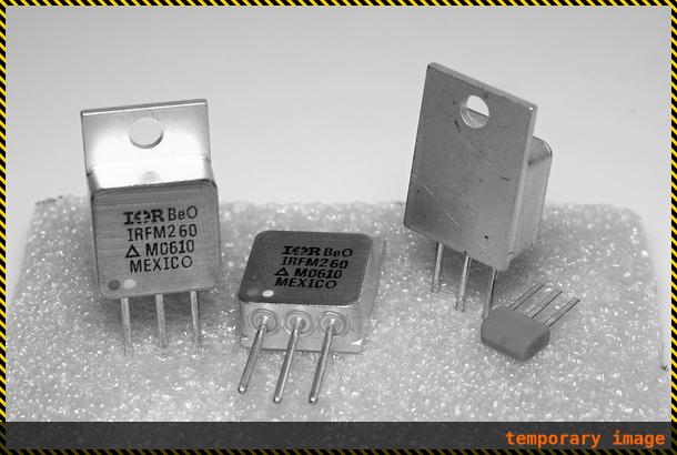
The first thing you have to do is tell the stepper motor drivers what is the current rating for your stepper motors is. To drive the stepper motor correctly, the driver has to know the motor’s current rating.
Each stepper motor model has a precise current rating. You can drive your stepper motor at a lower current, which will make it more silent, but also less powerful. But you cannot drive the motor at a higher current than it is rated at. This would cause overheating, and possibly skipped steps.
The rating is often written on your stepper motor’s label (see picture on the right). If it is not, you can get it by googling the stepper motor model number, or by contacting your seller or manufacturer.
Once you have the correct rating, you can set the corresponding parameter in the configuration file.
Smoothie has a funny way of naming stepper motor drivers. Instead of naming them X, Y or Z, because this makes no sense in non-cartesian robots like delta robots, we name the drivers using Greek letters so they are arm application agnostic:
| Label on the Smoothieboard | Axis in a Cartesian machine | Greek letter | Current setting configuration option |
|---|---|---|---|
| M1 | X (left-right) | α (alpha) | |
| M2 | Y (front-back) | β (beta) | |
| M3 | Z (up-down) | γ (gamma) | |
| M4 | E0: First extruder | δ (delta) | |
| M5 | E1: Second extruder | ε (epsilon) |
Now, as described in the “Unboxing” paragraph, connect the board to your computer, open the “config” file with a text editor, and change the configuration value for each stepper motor driver to the correct value.
For example, if your alpha stepper motor has a current rating of 1.68A, edit the corresponding line to read:
alpha_current 1.68 # X stepper motor current
[current control]
alpha.current = 1.68             # X stepper motor current
Do this for each stepper motor you have to connect to the board. (If you have a Cartesian robot, see which motor connects to which stepper driver in the array above. If you use another type of arm solution, see the specific documentation.)
Steps per millimeter
A stepper motor driver operates in steps. It moves a certain number of steps in one direction, then a certain number of steps in another. You think in millimeters. You want your machine to go to a certain position in millimeters, then another position in millimeters.
You need Smoothieboard to convert the millimeters you ask of it, into steps the stepper motor driver understands.
That conversion depends on your exact arm solution. The most common, and the simplest, is the Cartesian arm solution, and it is the one we will focus on here. Documentation for other arm solutions can be found separately.
In the case of a Cartesian arm solution, you simply convert a certain number of millimeters to a certain number of steps. That is the
To compute it, you must multiply a certain number of factors.
- The object you move moves a certain number of millimeters for each rotation of the stepper motor. (This depends on the characteristics of the belt/pulley, or lead-screw system you are using.)
- The stepper motor moves a certain number of full steps per rotation. That is usually 200. (But it can be 400.)
- Each step is divided by the stepper motor driver into a certain number of microsteps. It is that number, and not the number of full steps, that we want. Smoothieboard V1.1 always divides steps into 32 microsteps. (16 for older smoothieboards).
The formula is as follows:
steps per millimeter = ((full steps per rotation) x (microsteps per step)) / (millimeters per rotation)
To help you, there is an awesome calculator by the awesome Josef Prusa: http://calculator.josefprusa.cz/
Once you know the correct value for a given stepper motor driver, set it in the config file.:
alpha_steps_per_mm 80 # Steps per mm for alpha stepper
[actuator]
alpha.steps_per_mm = 80               # Steps per mm for alpha stepper
Do this for each stepper motor driver.
In the case of your extruder stepper motor, the principle is the same, but the value is
Here is a good video on steps per millimeters:
Direction
It is now time to test your stepper motors. For this, you will need to use host software like Pronterface or the web interface.
Now connect to your Smoothieboard over the serial interface. Power your machine on by plugging the PSU into the wall.
Now you need to move an axis to make sure the stepper motor is turning in the right direction. In Pronterface, click near the yellow arrow marked “+X”.
Your X axis will move. If it moved to the right, great! Everything is fine, and you have nothing to change. If it moved to the left, you need to invert the direction of that axis.
You do this by editing the configuration file, and inverting the direction pin for that stepper motor driver:
alpha_dir_pin 0.5 # Pin for alpha stepper direction
Becomes:
alpha_dir_pin 0.5! # Pin for alpha stepper direction
[actuator]
alpha.dir_pin = 0.5              # Pin for alpha stepper direction
Becomes:
[actuator]
alpha.dir_pin = 0.5!             # Pin for alpha stepper direction (inverted)
This is for your axes. In the case of your extruder, the config value is
Save the config file, reset the Smoothieboard, connect again using Pronterface. Now the axis will move in the right direction.
Do this for each axis.
If you have a moving bed in the Y axis for example, as opposed to a moving tool, be careful: what matters is the direction of the head relative to the bed, not the direction of the bed relative to the machine.
It's very common to get confused and invert your Y axis on moving bed machines (or not invert it when it should be).
Basically, if an asymmetrical object looks like the model when it is printed, then your Y axis is correct, otherwise you need to change your configuration.
Arm Solutions
On a typical “Cartesian” machine, each actuator (a motor and a linear rail, named alpha, beta, gamma) corresponds to an axis (like X, Y, and Z).
However, on other machines, the position in Cartesian space (X, Y, Z) must be converted, using math, into a more complex position for the actuators.
This is the case, for example, of linear delta (often just called “delta”) machines.
Supported Arm Solutions
Smoothieware supports multiple arm/motion solutions to accommodate different machine architectures. The table below shows which solutions are available in each firmware version:
| Setting | v1 | v2 | Description | Documentation |
|---|---|---|---|---|
| ✅ | ✅ | Standard X/Y/Z configuration where each motor directly controls one axis | Cartesian | |
| ✅ | ✅ | Three vertical linear rails in triangular configuration (Rostock, Kossel) | Delta | |
| ✅ | ✅ | Crossed-belt system where both motors contribute to X and Y movement | HBot/CoreXY | |
| ✅ | ✅ | Crossed-belt variant where both motors contribute to X and Z movement | CoreXZ | |
| ✅ | ✅ | SCARA-style robotic arm with two parallel rotary joints | Morgan SCARA | |
| ✅ | ✅ | Delta variant using rotating joints instead of linear slides (experimental) | Rotary Delta | |
| ✅ | ❌ | Cartesian system rotated by a specified angle (v1 only) | Rotatable Cartesian |
linear_delta,delta,rostock, orkosselall select Linear Deltahbotorcorexyboth select HBot (they use the same implementation)morganselects Morgan SCARA
Configuration
To configure your machine for the right type, see its specific page linked in the table above.
Each arm solution has its own configuration parameters and requirements. The
V1 Configuration (flat namespace):
arm_solution cartesian
For example, to configure a linear delta printer:
arm_solution linear_delta
V2 Configuration (INI sections):
[motion control]
arm_solution = cartesian
For example, to configure a linear delta printer:
[motion control]
arm_solution = linear_delta
If no arm solution is specified, cartesian is used by default.
Extruder
Extruders are used to push plastic filament through a hotend, to achieve the awesome feat of 3D Printing.
This module controls the motor that pushes the filament, it does not take care of the hotend itself, which is the job of TemperatureControl.
Steps Per Millimeter Configuration:
The most important parameter to get your extruder module to work properly is the steps per millimeter setting:
extruder.hotend.steps_per_mm 140
[extruder]
hotend.steps_per_mm = 140
You can create as many Extruder modules as you want (although you may run out of memory and Smoothie will no longer boot), as long as you give them different module names.
You can name those modules whatever you want (as long as you stick to only alphanumerical characters).
make AXIS=6.
Configuration
Steps per millimeter
We need to find the number of steps the stepper motor drivers have to generate in order to move the filament 1 millimeter.
This value depends on your stepper motor, the microstepping on your stepper motor drivers, the gear reduction ratio on the extruder assembly if any, and the diameter of your hobbed pulley/bolt.
A very good guide on how to find this value can be found here: Triffid Hunter’s Calibration Guide.
extruder.hotend.steps_per_mm 140
[extruder]
hotend.steps_per_mm = 140
Filament diameter
This is an optional parameter for those who want to use volumetric extrusion, but are too lazy to do their own math. ;)
Simply enter the machine’s filament diameter here and set your slicer’s filament diameter to 1.128379mm (2*sqrt(1/pi)) and enjoy portable gcode!
Further explanation can be found in Triffid Hunter’s guide, linked above.
Note that when firmware retraction is specified via {::nomarkdown}
In the current master builds, only print moves have E specified in mm³, retract or extrude only moves are still in mm. The change in edge is to be more compliant with other firmwares and user expectations.
extruder.hotend.filament_diameter 3.0
[extruder]
hotend.filament_diameter = 3.0
The filament diameter can also be saved at runtime with this M code:
| Set E units for volumetric extrusion - D |
and saved with
Firmware Retract
Note this is optional, you are not obligated to set this up, but it is a nice feature if you want to use it.
The amounts of extrusion and speed can be set with the following M codes:
| set retract length S[positive|mm] F[feedrate|mm/min] Z[additional|zlift/hop] Q[zlift|feedrate mm/min] | ||
| set retract recover length S[positive|mm surplus to the M207 S*] F[feedrate|mm/min] |
or can be set in config with the following settings:
extruder.hotend.retract_length                  3       # retract length in mm
extruder.hotend.retract_feedrate                45      # retract feedrate in mm/sec
extruder.hotend.retract_recover_length          0       # additional length for recover
extruder.hotend.retract_recover_feedrate        8       # recover feedrate in mm/sec (should be less than retract feedrate)
extruder.hotend.retract_zlift_length            0       # zlift on retract in mm, 0 disables
extruder.hotend.retract_zlift_feedrate          6000    # zlift feedrate in mm/min (Note mm/min NOT mm/sec)
[extruder]
hotend.retract_length = 3                       # retract length in mm
hotend.retract_feedrate = 45                    # retract feedrate in mm/sec
hotend.retract_recover_length = 0               # additional length for recover
hotend.retract_recover_feedrate = 8             # recover feedrate in mm/sec (should be less than retract feedrate)
hotend.retract_zlift_length = 0                 # zlift on retract in mm, 0 disables
hotend.retract_zlift_feedrate = 6000            # zlift feedrate in mm/min (Note mm/min NOT mm/sec)
These can be set differently for each extruder defined.
Pins
As all stepper motors, the extruder stepper motor needs 3 pins to be controlled: step, direction, and enable (See Pin Reference and Pinout):
1st Extruder (delta, or M4)
extruder.hotend.step_pin                        2.3
extruder.hotend.dir_pin                         0.22
extruder.hotend.en_pin                          0.21
[extruder]
hotend.step_pin = PD3
hotend.dir_pin = PD4
hotend.en_pin = PD5
2nd Extruder (epsilon, or M5)
extruder.hotend2.step_pin                       2.8
extruder.hotend2.dir_pin                        2.13
extruder.hotend2.en_pin                         4.29
You can make your extruder module use any other stepper motor driver, or even an external stepper motor driver, simply by providing the adequate pins for that driver, see Pinout.
Current
On boards which feature current control of the stepper motor drivers (Smoothieboard or 4pi), you have to set that value for the extruder too.
This is handled by the Currentcontrol module, but usually, the line for the configuration of a given stepper motor is written along with its pins, for clarity.
delta_current 1.5
[tmc2660]
delta.current = 1500                            # Current in milliamps (mA), not Amps
[tmc2660] or [tmc2590] section depending on your driver type.
Set the value to the exact value your stepper motor is rated for (or less, for less noise, but less torque).
Setting the current to a value higher than the recommended one causes overheating, and skipped steps.
Example
Here is an example of a common configuration and wiring of an extruder with a Smoothieboard.
This example setup is of an extruder (stepper motor) connected to the M4 stepper motor driver.
If your machine has multiple extruders, you also want to look at multiple-extruders.
Configuration
The default Smoothie configuration example contains an example extruder section, this means you do not need to create a new one, but you can just re-use the sample one.
The configuration looks like this:
## Extruder module configuration
# See /extruder
extruder.hotend.enable                          true    # Whether to activate the extruder module at all. All configuration is ignored if false
extruder.hotend.steps_per_mm                    140     # Steps per mm for extruder stepper
extruder.hotend.acceleration                    500     # Acceleration for the stepper motor mm/sec²
extruder.hotend.max_speed                       50      # Maximum speed in mm/s

extruder.hotend.step_pin                        2.3     # Pin for extruder step signal
extruder.hotend.dir_pin                         0.22    # Pin for extruder dir signal (add '!' to reverse direction)
extruder.hotend.en_pin                          0.21    # Pin for extruder enable signal

delta_current                                   1.5     # Current setting in Amperes for this motor driver
## Extruder module configuration
# See /extruder
[extruder]
hotend.enable = true                            # Whether to activate the extruder module at all
hotend.steps_per_mm = 140                       # Steps per mm for extruder stepper
hotend.step_pin = PD3                           # Pin for extruder step signal
hotend.dir_pin = PD4                            # Pin for extruder dir signal (add '!' to reverse direction)
hotend.en_pin = PD5                             # Pin for extruder enable signal

[actuator delta]
acceleration = 500                              # Acceleration for the stepper motor mm/sec²

[motion control]
max_speed = 50                                  # Maximum speed in mm/s

[tmc2660]
delta.current = 1500                            # Current setting in milliamps for this motor driver
Now that your extruder is configured, you can wire it:
Wiring
Wiring your extruder stepper motor is very similar to how you wire your X, Y, and Z stepper motors (see adequate documentation):
you just wire the 4 wires of the stepper motor, to the output connector of the M4 stepper motor driver.

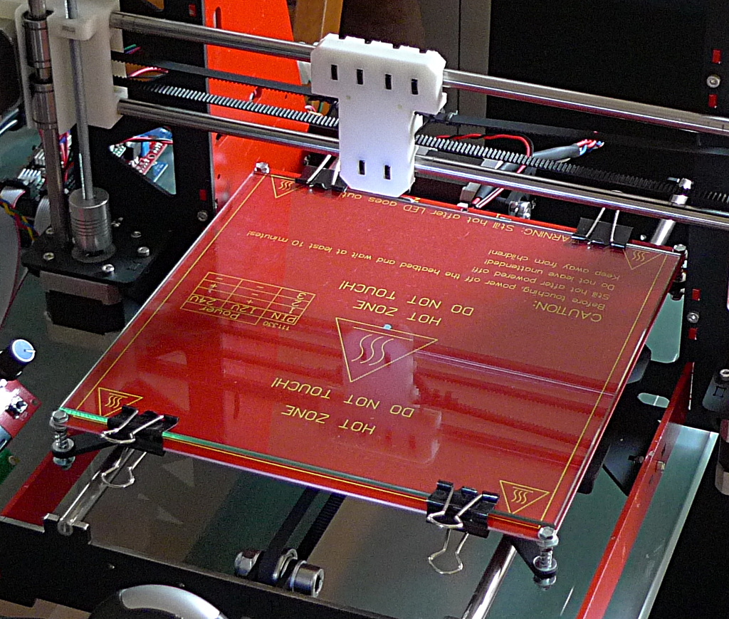
A hotend contains a thermistor and a heating element in its heating block.
Temperature control
In a 3D printer, you heat thermoplastics.
There are two different parts in which you want to do that:
First, the hot-end heats the plastic to the point where it is liquid enough to go through the nozzle.
Second, the heated bed (in only some printers), on which the first layer is deposited, is heated to allow for better sticking of the plastic to the bed, and more uniform temperature in the part while printing.
For detailed information about temperature control in Smoothie, you can look at this part of the documentation: TemperatureControl
The process is essentially the same to wire and control a hot-end, or a heated bed, and is as follows:
Thermistor
A thermistor’s resistance changes with temperature.
By reading that resistance, we can determine the temperature of a hot-end or a heated bed.
This allows Smoothie to turn the heater on or off depending on the temperature it reads, to achieve the desired temperature.

There are 4 thermistor inputs, close to the SD card slot.
To wire the thermistor, take the two wires from the thermistor on your hot-end or heated bed, and connect them to one of the pairs of thermistor inputs on the Smoothieboard. Each input is two pins, one for each thermistor wire. There is no polarity to respect.
Smoothieboard has 4 thermistor inputs total, meaning a line of 8 pins on the edge of the board. Polarity is not important for thermistors.
When reading temperature, never use the normal ground to read temperatures, always use the AGND connections provided on the thermistor inputs.
This also means you cannot "share the ground" on wires going to your hotend, as some users sometimes do to "save wires". This is a very bad idea and will cause a lot of problems.
By convention (meaning that if you wire things according to the way it is specified in the default configuration file, you do not need to edit the configuration file as it will already be correct),
- Hot-end thermistor connects to T0
- Heated bed thermistor connects to T1
In the default configuration file, the thermistor pins are set up using that convention:
temperature_control.hotend.thermistor_pin    0.23             # Pin for the thermistor to read (here T0)
temperature_control.bed.thermistor_pin       0.24             # Pin for the heated bed to read (here T1)
You can, however, use any thermistor pin you want for any temperature control module you want.

Thermistors come in all shapes and sizes.
Thermistor Choice
Different models of thermistors are used in hotends or heated beds, and each type translates temperature into resistance differently. It’s essential to inform Smoothie about the specific thermistor model you have to ensure accurate temperature readings.
This configuration is done using the thermistor option in the configuration file. You provide the name of your thermistor, and Smoothie will handle the math accordingly.
V1 Configuration (flat namespace):
temperature_control.hotend.thermistor EPCOS100K
V2 Configuration (INI sections):
[temperature control]
hotend.thermistor = EPCOS100K
Currently, Smoothie recognizes the following thermistor models:
| Name | Beta for 0-80°C | Beta for 185-230°C | I for Steinhart Hart | J for Steinhart Hart | K for Steinhart Hart | Part number |
|---|---|---|---|---|---|---|
EPCOS100K |
4066 | 4193 | 0.000722378300319346F | 0.000216301852054578F | 9.2641025635702e-08F | B57540G0104F000 |
Honeywell100K |
3974 | 4385 | 0.000596153185928425F | 0.000231333192738335F | 6.19534004306738e-08F | 135-104LAG-J01 |
Semitec |
4267 | 4375 | 0.000811290160145459F | 0.000211355789144265F | 7.17614730463848e-08F | 104GT-2 |
Honeywell-QAD |
0.000827339299500986F | 0.000208786427208899F | 8.05595282332277e-08F | 135-104QAD-J01 | ||
Semitec-104NT4 |
0.000797110609710217F | 0.000213433144381270F | 6.5338987554e-08F | 104NT-4R025H42G | ||
RRRF100K |
3960 | |||||
RRRF10K |
3964 | |||||
HT100K |
3990 |
Unknown Thermistor
If your thermistor is not recognized by Smoothie, you can define the parameters manually in the configuration file using either the beta value or the Steinhart Hart algorithm.
Using Beta Values
Set the beta value in the configuration file:
V1 Configuration:
temperature_control.hotend.beta 4066 # set beta for thermistor
V2 Configuration:
[temperature control]
hotend.beta = 4066   # set beta for thermistor
This makes beta values generally suitable for heated beds but not for hotends.
If the thermistor is 100K ohms at 25°C, this setting is usually sufficient. Additional settings like r0, t0, r1, r2 are not typically needed as the defaults work well.
If you’re unsure about your thermistor model, contact the designer or seller of your 3D printer, hotend, or heated bed to obtain the specifications and beta value.
Using the Steinhart Hart Algorithm
This is the preferred method. Set the Steinhart Hart coefficients in the configuration file:
V1 Configuration:
temperature_control.hotend.coefficients 0.000722376862540841,0.000216302098124288,0.000000092640163984
V2 Configuration:
[temperature control]
hotend.coefficients = 0.000722376862540841,0.000216302098124288,0.000000092640163984
To determine the Steinhart Hart coefficients for your thermistor, please refer to the SteinhartHart page.
Alternatively, if you have the temperature curve for your thermistor, you can define three points on that curve and let Smoothie calculate the coefficients:
V1 Configuration:
temperature_control.hotend.rt_curve 20.0,126800,150,1360,240,206.5
V2 Configuration:
[temperature control]
hotend.rt_curve = 20.0,126800,150,1360,240,206.5
Heating element
Now that Smoothie can read the temperature, it needs a way to heat things and maintain a desired temperature.
This is the heating element.
On a hot-end, that is usually a resistor or a cartridge heater, on a heated bed, that is usually a PCB plate designed to have the right resistance, or a kapton heated bed.
Because of its resistance, when power is applied to a heater, the heater consumes energy to generate heat.
These heating elements need to be connected to Smoothieboard on a port that allows Smoothie to turn them ON or OFF as needed. This is done by the use of MOSFET that takes a digital input signal, and, depending on its value, lets current pass or not.
MOSFETs
Smoothie has up to 6 MOSFET controls (6 on 5X, 4 on 4X, and 2 on 3X).
The MOSFETs act as switches to ground: loads must be connected between the power source and the MOSFET switched terminal.
When the MOSFET is switched on, power will be applied to the load.
When the MOSFET is switched off, power will be removed, because one load terminal will be essentially disconnected and current cannot flow.
The exception being inductive load ‘flyback’ switching transients, discussed above.
Connect your PSU to the power input connector for those FETs (providing power to the load), and connect your power-consuming element (be it heating element, spindle, etc.) between the power output terminal and the MOSFET terminal.
Smoothie connects/disconnects the element’s ground as needed to maintain temperature or as requested by G-codes.
There are three main pairs of MOSFETs on the board:
MOSFET Overview
Smoothieboard v2 has a simplified and safer MOSFET architecture compared to v1:
| Output Type | Count | Current | Purpose |
|---|---|---|---|
| Low-Current FETs | 4 | ~5A each | Hotend1, Hotend2, Fan1, Fan2 |
| Bed FET | 1 (2× parallel) | ~10-12A | Heated bed |
| SSR Outputs | 2 | Milliamps | Solid-state relay control |
All MOSFET outputs are powered from the VFET power input (2× XT30 connectors, 30A total).
Key Safety Feature: High-Side PFET Watchdog
The 4 low-current FETs share a common +VFET rail controlled by a high-side P-channel MOSFET (PFET) watchdog. The firmware can instantly kill power to all 4 outputs if a thermal runaway or fault is detected.
How it works:
- All 4 low-current FETs (hotends, fans) connect to a shared +VFET power rail
- This rail is controlled by a high-side PFET watchdog
- If any low-side FET fails shorted (stuck ON), the high-side PFET can still disconnect power
- Provides an additional layer of protection against thermal runaway
Bed FET Independence:
- The heated bed FET is NOT controlled by the high-side PFET watchdog
- This is deliberate: allows the bed to remain on even if other FETs are shut down
- Bed thermal runaway protection is handled directly by firmware
Low-Current FETs (Hotends, Fans)
| Specification | Value |
|---|---|
| Outputs | 4 (hotend1, hotend2, fan1, fan2) |
| Current Rating | ~5A per output |
| Voltage | Up to 24V |
| Power Source | Shared +VFET rail |
| Safety | High-side PFET watchdog |
| Control | PWM capable (firmware-controlled frequency) |
| LED Indicators | Yes (per output) |
Bed FET
| Specification | Value |
|---|---|
| Configuration | 2× MOSFETs in parallel |
| Combined Current | ~10-12A |
| Voltage | Up to 24V |
| Power Source | Direct from VFET (not through PFET watchdog) |
| Control | PWM capable |
| LED Indicator | Yes |
200W bed @ 12V: 16.7A - Consider using an external SSR
200W bed @ 24V: 8.3A - Within bed FET capacity
SSR Outputs
| Specification | Value |
|---|---|
| Outputs | SSR1, SSR2 |
| Type | Logic-level (3.3V or 5V signal) |
| Current | Milliamps (for SSR coil drive) |
| Use Cases | Solid-state relay control, auxiliary outputs |
Use SSR outputs to control external solid-state relays for:
- High-power heated beds (>12A)
- AC-powered heaters
- Other high-current loads
Power LED Indicators
Each MOSFET output has its own LED indicator showing when it’s active:
- Hotend1 LED: Hotend 1 heater active
- Hotend2 LED: Hotend 2 heater active
- Fan1 LED: Fan 1 active
- Fan2 LED: Fan 2 active
- Bed LED: Heated bed active
-
Big MOSFET pair: Their outputs are labeled P
2.7 and P2.5 on the schematic, the input connector for them is found between them. They are found on the 4X and 5X boards. To power those MOSFETs, you need to provide them with power by wiring their power input to the power supply. -
Small MOSFET pair: Their outputs are labeled P
2.6 and P2.4 on the schematic, the input connector for them is found by their side, between P2.6 and P1.23 . They are found on all of the boards. To power those MOSFETs, you need to provide them with power by wiring their power input to the power supply. -
Mixed MOSFET pair: Their outputs are labeled P
1.22 and P1.23 on the schematic. The pair is called “mixed” because it consists of one big MOSFET and one small MOSFET. They do not have a specific input, they take power directly from VBB (the Stepper motors power input described in the Stepper Motors chapter). To power those MOSFETs, you need to provide them with power by wiring their power input (which is the same as the one for the stepper motors) to the power supply.
This allows you to use different voltages for different things if you want, and makes it easier to use more current as the current is shared between more connectors. It does mean wiring one or two more connectors though.
If you are trying to control MOSFETs and they are not turning on, make sure you provided power to their power input.
MOSFETs list:
| MOSFET group | MOSFET name | Controlling pin | Output connector | Input method | Voltage | Current |
|---|---|---|---|---|---|---|
| Big MOSFETs | First big MOSFET | X15 | Big MOSFETs power input X13 | 12-24V | 12.5A max | |
| Big MOSFETs | Second big MOSFET | X10 | Big MOSFETs power input X13 | 12-24V | 12.5A max | |
| Small MOSFETs | First small MOSFET | X7 | Small MOSFETs power input X6 | 12-24V | 3A max | |
| Small MOSFETs | Second small MOSFET | X8 | Small MOSFETs power input X6 | 12-24V | 3A max | |
| Mixed MOSFETs | Third big MOSFET | X16 | VBB (motor) input | 12-24V | 12.5A max | |
| Mixed MOSFETs | Third small MOSFET | X9 | VBB (motor) input | 12-24V | 3A max |
MOSFETs diagram
+ on that connector to + on your PSU, and - to - on the PSU.
Heater elements, however, do not have a polarity, so you do not have to worry about polarity on the outputs.
If you are using another output element like a Peltier or a Spindle, you need to be careful to respect the polarity for the outputs too.
Never use the big MOSFETS for more than 12.5A (and monitor connector and MOSFET temperatures at that current use, too much heating can be a sign of a bad wire connection), and the small MOSFETS should never be used for more than 3A.
Trying to power a 40W (or more) hotend cartridge heater at 12V with the small FETs will destroy them, usually locking (melting) them to the “ON” state (shorted) and possibly destroying the circuitry driving the MOSFET gate.
If you need to control more than 12 Amps, you cannot do it with one of the MOSFETS on board, however, you can use a Solid State Relay.
For information see the Solid State Relay Appendix on this page.
There is an alternative, however (for currents up to 2 Amps or 4 Amps). For each pair, you can use jumpers (one jumper for the small MOSFETS pair (JP28), two parallel jumpers for the two big MOSFETS pair (JP11 and JP27)).
If you solder the pins for those OR connect a jumper to those pins, closing the circuit to VBB (the stepper motors power input), allowing you to take the power from those MOSFETS from the same place as the stepper motors do.
In the case of the big MOSFETS, you have to solder and put in place two jumpers, in parallel, in order to handle more current.
This means you cannot use this way of powering your MOSFETS if you are going to use more than 2A (for the small MOSFETS) or 4A (for the big MOSFETS, with both jumpers used, for 2 x 2A).
Do not use the jumpers to power a heated bed, for example, as it uses much more than 4A.
Wiring MOSFET Outputs
Power Connection
All MOSFET outputs on Smoothieboard v2 are powered from the VFET power input:
Unlike v1, Smoothieboard v2 has a single VFET power input (2× XT30 connectors) that powers ALL MOSFET outputs. No separate power inputs for different MOSFET groups!
Wiring steps:
- Connect your 12-24V power supply to the VFET XT30 connectors
- Connect your heaters/fans between the MOSFET output terminals and ground
- That’s it - no jumpers or multiple power connections needed!
MOSFET Output List
| Output | Type | Current | Typical Use |
|---|---|---|---|
| Hotend1 | Low-current FET | ~5A | First hotend heater |
| Hotend2 | Low-current FET | ~5A | Second hotend heater |
| Fan1 | Low-current FET | ~5A | Part cooling fan |
| Fan2 | Low-current FET | ~5A | Auxiliary fan |
| Bed | Dual parallel FETs | ~10-12A | Heated bed |
| SSR1 | Logic output | mA | External SSR control |
| SSR2 | Logic output | mA | External SSR control |
Polarity and Safety
+ on your PSU to the + terminal on the XT30 connectors.
Heater elements (resistive) do not have a polarity, so you do not have to worry about polarity on the outputs.
If you are using a Peltier element or a DC motor, you need to respect the polarity for the outputs.
High-Current Loads (>12A)
If you need to control more than 10-12A (the bed FET limit), use the SSR outputs to control an external Solid State Relay:
- SSR1/SSR2 provide logic-level signals to drive SSR coils
- Use a properly rated SSR for your load (e.g., 40A SSR for AC-powered heated beds)
- SSRs are recommended for AC mains-powered heaters
For information see the Solid State Relay Appendix.
Heated beds are often made out of a rigid, or flexible (kapton) PCB.
Example
Let’s say you want to connect a heated bed to your Smoothieboard.
First, wire the thermistor to the thermistor input.
Then, find out (from the Internet, or your seller/manufacturer) the current rating for that heated bed.
In this example it will be the classical RepRap PCB plate Heatbed.
Ours has an 11A current rating, this means we cannot use it with a small MOSFET, and we need to wire it to a big MOSFET.
We connect our PSU to the power input for the big MOSFETS pair (don’t forget to check the labels on the board for polarity).
Then we connect the two wires from the PCB bed to one of the big MOSFETS out. Polarity is not important here.
Because this is the heated bed, we connect it to the P2_7 (pin
For the hot-end, the default output is P2_4 (pin
To set a different MOSFET output for the bed or the hot-end, you have to edit the configuration file to the digital output pin corresponding to your chosen MOSFET. These are the lines you would have to edit:
temperature_control.hotend.heater_pin        2.7              # Pin that controls the heater cartridge for the hot-end
temperature_control.bed.heater_pin           2.5              # Pin that controls the heated bed
To help you figure out what is what, here is a recapitulating table:
MOSFETs Table
This page documents the MOSFET outputs available on Smoothieboard and their specifications.
MOSFETs are used to control high-power devices like heated beds, hotends, fans, and other accessories.
MOSFET Specifications
| MOSFET Pair | Big MOSFETS | Small MOSFETS | Mixed MOSFETS | |||
|---|---|---|---|---|---|---|
| Label on diagram | P |
P |
P |
P |
P |
P |
| Digital output pin | ||||||
| Power Input | Between P |
Between P |
Taken from VBB | |||
| Size | Big | Big | Small | Small | Big | Small |
| Maximum current | 12A | 12A | 3A | 3A | 12A | 3A |
| Used by default for | Heated bed | Hotend 0 | Fan | Hotend 1 |
Understanding MOSFET Pairs
Smoothieboard has three MOSFET pairs:
Big MOSFETs Pair (P2.7 and P2.5 )
- Current capacity: 12A each
- Power input: Shared between the two outputs (between P
2.7 and P2.5 terminals) - Typical use: Heated bed (high current devices)
- Note: Both outputs share the same power input
Small MOSFETs Pair (P2.4 and P2.6 )
- Current capacity: 3A each
- Power input: Shared between the two outputs (between P
2.6 and P1.23 terminals) - Typical use: Hotend 0 and fan (moderate current devices)
- Note: Both outputs share the same power input
Mixed MOSFETs Pair (P1.23 and P1.22 )
- Current capacity: P
1.23 : 12A, P1.22 : 3A - Power input: Taken directly from VBB (main power supply)
- Typical use: P
1.23 for Hotend 1, P1.22 for accessories - Note: These outputs use the main VBB power supply
| Output | Controlling Pin | Current Rating | Typical Use |
|---|---|---|---|
| Hotend A | ~5A | Primary hotend heater | |
| Hotend B | ~5A | Secondary hotend heater | |
| Fan 1 | ~5A | Part cooling fan | |
| Fan 2 | ~5A | Auxiliary fan | |
| Bed | ~10-12A | Heated bed (dual parallel FETs) | |
| SSR1 | Logic output | mA | External SSR control |
| SSR2 | Logic output | mA | External SSR control |
Understanding MOSFET Outputs
Smoothieboard v2 has a simplified MOSFET architecture:
Low-Current FETs (Hotend A, Hotend B, Fan 1, Fan 2)
- Current capacity: ~5A each
- Power input: Shared VFET rail (2× XT30 connectors)
- Safety feature: High-side PFET watchdog can cut power to all 4 outputs
- Note: All share the same power source, controlled by safety watchdog
Bed FET
- Current capacity: ~10-12A (dual parallel MOSFETs)
- Power input: Direct from VFET (not through PFET watchdog)
- Typical use: Heated bed
- Note: Independent of safety watchdog for bed stability
SSR Outputs
- Current capacity: Milliamps (logic level signals)
- Use: Control external solid-state relays for high-power loads
Important Safety Notes
Configuration
To configure a MOSFET output in your config file, use the appropriate pin number from the “Digital output pin” row.
Example for configuring a heated bed on P
temperature_control.bed.heater_pin 2.7
Example for configuring a hotend on P
temperature_control.hotend.heater_pin 2.4
Example for configuring a heated bed on P
[temperature_control.bed]
heater_pin = 2.7
Example for configuring a hotend on P
[temperature_control.hotend]
heater_pin = 2.4
Related Documentation
- Smoothieboard - Main board documentation
- Temperature Control - Configuring heaters
- Pinout - Complete pinout diagram
- How to Wire - Wiring tutorials and best practices
Testing
Once your thermistor is connected, and both the power input and the heater elements are plugged in, you are ready to test your temperature controller.
To do this, reset your Smoothieboard, then connect to it using host software like Pronterface, or using the web interface.
Now connect to your Smoothieboard over the serial interface.
Power your machine on by plugging the PSU into the wall.
If anything burns or smells funny, turn everything off immediately and investigate.
The heaters are off by default when Smoothie starts. Check that they are not heating (one indication of the heater being ON is if the LED near the MOSFET is lit up, the other being checking the heater itself), if they are heating, something is wrong, turn everything off immediately and investigate.
Now, in Pronterface, set the temperature for either your bed or your hot-end, depending on what you are testing (wire and test only one at a time for easier problem investigation) at a low temperature (20°C above room temperature is a good idea), and monitor temperature to see if the temperature rises. If it does rise, everything is fine. If not, turn everything off immediately and investigate.
Once you know the heater works correctly, there is still some tuning to do: tuning your PID settings.
PID
Temperature Control PID
Why PID is Important
PID is crucial for stable temperature control.
Without PID, a simple way to control temperature would be:
- If temperature too cold, turn heater on
- If temperature too hot, turn heater off
But there is a big problem with that method.
Due to temperature not traveling instantly from the heater to the thermistor, when the thermistor reads a given temperature, the heater is already hotter than what the thermistor reads.
This overshooting is something we do not want.
It means reaching temperatures that could be undesirable, and it means you will not be able to correctly stabilize the temperature.
What is PID?
The solution to this is PID.
It uses some math, allowing us to correct those problems by turning the heater on and off in a smarter sequence.
PID stands for:
- Proportional - Responds to current error
- Integral - Responds to accumulated error over time
- Derivative - Responds to rate of change of error
Configuring PID Values
The P, I, and D factors are configured in your config file as follows:
V1 Configuration:
temperature_control.hotend.p_factor     100
temperature_control.hotend.i_factor     0.1
temperature_control.hotend.d_factor     100
V2 Configuration:
[temperature control]
hotend.p_factor = 100
hotend.i_factor = 0.1
hotend.d_factor = 100
Finding the Right Values
The really tricky thing is to find the right values for these 3 factors.
The default ones are most probably wrong for your setup.
So unless you have been given those values with your hardware, or you are a PID grand-master, you will need some help finding the optimal values.
PID Auto-Tuning
To auto-tune your PID values:
- Start the auto-tune process:
M303 E0 S200E0 specifies the hotend (useE1 ,E2 , etc. for other extruders)S200 is the target temperature (adjust to your typical printing temperature)
-
Wait for completion - The process will take several minutes as it cycles the heater and measures response
-
Review the results - The auto-tune will output the calculated PID values
-
Update your config - Add the new values to your config file
- Test - Heat to your target temperature and verify stability
Manual PID Tuning
If auto-tuning doesn’t work well for your setup, you can manually tune:
Starting Values
Begin with conservative values:
V1 Configuration:
p_factor = 100
i_factor = 0.1
d_factor = 100
V2 Configuration:
[temperature control]
hotend.p_factor = 100
hotend.i_factor = 0.1
hotend.d_factor = 100
Tuning Process
- Adjust P first:
- Too low: Slow to reach temperature, large oscillations
- Too high: Fast oscillations, unstable
- Then adjust I:
- Too low: Won’t eliminate steady-state error
- Too high: Overshoots, slow to stabilize
- Finally adjust D:
- Too low: More overshoot
- Too high: Very sensitive, noisy
Different Heater Types
Different heater configurations may require different tuning approaches:
High-Power Heaters
High-power heaters (like cartridge heaters) may need:
- Lower P values
- Higher D values
- Faster response times
Low-Power Heaters
Low-power heaters (like resistive wire) may need:
- Higher P values
- More integral action
- Slower response tuning
Heated Beds
Heated beds typically need:
- Much lower P values due to large thermal mass
- More integral action for steady-state
- Lower D values due to slow thermal response
Troubleshooting PID Issues
Temperature Oscillates
Symptom: Temperature swings up and down around target
Solutions:
- Reduce P factor
- Increase D factor
- Check for good thermal coupling between heater and thermistor
Slow to Reach Temperature
Symptom: Takes a long time to heat up
Solutions:
- Increase P factor
- Check PWM frequency settings
- Verify heater power is adequate
Overshoots Temperature
Symptom: Temperature goes past target then settles
Solutions:
- Reduce P factor
- Increase D factor
- Reduce I factor
Won’t Stabilize
Symptom: Can’t maintain steady temperature
Solutions:
- Increase I factor slightly
- Check for environmental factors (drafts, etc.)
- Verify thermistor is working correctly
Advanced Configuration
PWM Frequency
The PWM frequency can affect PID performance:
V1 Configuration:
temperature_control.hotend.pwm_frequency 1000
V2 Configuration:
[temperature control]
hotend.pwm_frequency = 1000
Higher frequencies (1000-4000 Hz) are typically better for solid-state relays and MOSFETs.
Bang-Bang Mode
For very simple setups, you can disable PID entirely:
V1 Configuration:
temperature_control.hotend.bang_bang true
V2 Configuration:
[temperature control]
hotend.bang_bang = true
This uses simple on/off control. Not recommended for most applications.
Further Reading
- Temperature Control module documentation
- Thermistor configuration
- Heater configuration
M303 G-code documentation (see supported G-codes)
Safety Notes
- Never leave heaters unattended during PID tuning
- Ensure thermal runaway protection is enabled
- Monitor temperatures closely during tuning
- Have a fire extinguisher nearby
- Stop immediately if anything seems wrong
PID autotuning
PID Autotuning
Smoothie can automatically tune (find) your P, I, and D factors using a process described here.
Here is an example of the G-code command used to launch PID autotune:
E0 is the number of the heater or bed temperature control module, determined by the order that they appear in the config file. Here it would be 0 for the hotend, and 1 for the bed.S190 is the temperature to autotune for. Use the temperature you will be using your heater at in real life. For a hotend here we use 190°C.
When you run the command, tuning begins:
Target: 190.0
Start PID tune, command is M303 E0 S190
T: Starting PID Autotune, M304 aborts
ok
T:  21.3/190.0 @80 1 0/8
T:  22.0/190.0 @80 1 0/8
T:  22.3/190.0 @80 1 0/8
T:  22.1/190.0 @80 1 0/8
Etc...
It continues for 3 to 8 cycles, heating up, cooling down. Then:
Cycle 4: max: 246.189, min: 227.627, avg separation: 0.418274
	Ku: 34.9838, Pu: 39.85
	Trying:
	Kp:  21.0
	Ki: 1.053
	Kd:   105
PID Autotune Complete! The settings above have been loaded into memory, but not written to your config file.
Now edit your configuration to use those three values (
Alternatively, you can also enter the following G-code:
Which will save the configuration values automatically in a configuration override file.
Learn more about configuration overrides here.
If sent over the web, the answers will accumulate in Smoothie's RAM and may crash it.
Heater safety
There are features you can configure to make sure that your temperature control module will detect when something is wrong, and stop the machine when that happens.
It is a good thing to read about these, and configure them as best as you can, because your house burning down is a very bad thing.
It is also a good thing to configure it well, because if you do not, it is possible Smoothie will think there is a problem when there is none, which can be annoying.
You can read more about temperature control safety here.
Example setup
This information is all very abstract.
Here is an example setup for a simple 3D printer with one hotend and one heated bed:
In this setup:
- The heated bed is 12A at 12V, or 144W
- The hotend is 3A at 12V, or 36W
We are going to use the first big mosfet to control the bed, it has a current limit of 12.5A so we are within limits.
We also need to provide power to the first big mosfet via the big mosfet power input.
We cannot however use the second big mosfet for anything, because if we did, we would go over the 12.5A limit of the big mosfet power input’s connector.
This is because the input must provide power to both outputs, so if we were for example to connect a 12.5A load to the first big mosfet, and a 2.5A load to the second big mosfet, the total passing through the big mosfet input would be 15A, which is over the 12.5A limit.
Therefore, we will use the first small mosfet to control the hotend. 3A is well within its limit.
Here again, we need to provide power to the small mosfet, via the small mosfet power input.
This means we will make 4 connections:
- Connecting the heated bed to the first big mosfet output
- Connecting the power supply to the big mosfet power input
- Connecting the hotend to the first small mosfet output
- Connecting the power supply to the small mosfet power input

Note how the mosfets need power provided to their power inputs
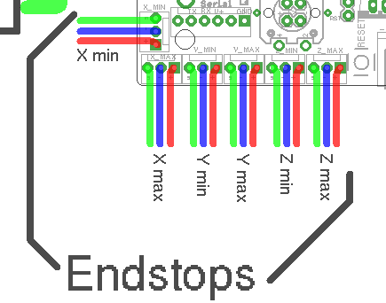
Endstops
It’s essentially just a switch
End-stops are small interrupters that you put at the end of each of your axes.
When you boot your machine up, Smoothie has no way of knowing the position of each axis.
When it starts a print, Smoothie moves the axis until it touches that interrupter, and when it is hit, it declares that that is position 0 for that axis. And does so for all axes.
This allows Smoothie to then precisely know where everything is relative to that initial position.
It is quite convenient as it saves you the hassle of actually moving the machine into that position when you want to start a print. Automation is great.
However, end-stops are not necessary, you could do without them. They are just so convenient that most machines use them.
End-stops can also be used as limit switches which prevent the machine from attempting to move beyond the physical limits of the axis (by pausing/stopping movement when triggered), see the Endstops page for details about configuring Smoothie to use End Stops as limit switches.
• Homing (move til endstop is hit)
• Hard endstops (stop when endstop is hit, which is optional)
• Soft endstop (once homed, do not go further than a set position, which is also optional)
This does not mean ANY kind of feature is missing, you can still do everything you expect, this is just a subtility in vocabulary and in how configuration is organized, that new users are generally fine with, except if they come from another system which has a different paradigm.
There are 6 of them, two for each axis
Mechanical endstop wiring
This will concentrate on the most common type of end-stops: the mechanical ones.
Other types exist like optical or hall-o sensors.
There are plenty of fun and futuristic endstop types around: optical, laser, magnetic, force-sensitive, infrared, inductive, etc...
However, please note that the general feedback from the community, is that most of those are either less precise, less repeatable, or much more difficult to get to "work right", compared to the classical "mechanical" endstop.
The mechanical endstop is actually likely the most precise, repeatable and easy to get to work option you have at your disposal. Just because these other options exist and have been explored by the community, does not mean they are better.
You might happen have a good reason to use a fancy endstop, but if you don't, it's likely a good idea to stick with a mechanical one.
Mechanical end-stops are simple interrupters: when not pressed, they do not let the current pass, when pressed, they let the current pass. By connecting a digital input pin on the Smoothieboard to the interrupter, and connecting the other side of the interrupter to Ground, the Smoothieboard can read whether or not it is connected to Ground, and therefore whether or not the end-stop is pressed.
Most mechanical end-stops have 3 connection points, to which you have to attach your wires:
- C: Common
- NO: Normally Open, meaning it is not connected to C when the interrupter is not pressed, and connected to C when the interrupter is pressed.
- NC: Normally Closed, meaning it is connected to C when the interrupter is not pressed, and not connected to C when the interrupter is pressed. {::nomarkdown}

You want to connect the Signal (green in the schematic) and Ground (blue in the schematic) pins for the end-stop on the Smoothieboard, to the C and NC connection points on the end-stop.
{:/nomarkdown}
For each endstop, we connect C to Signal and NC to Ground because this means the digital input pin (endstop connector) will be connected to Ground in its normal state and cut from Ground when the button is pressed. This approach is less prone to noise than the reverse. See here for more information.
Another positive effect of this approach is, that if a wire breaks for some reason you get the same signal as if the endstop is pressed. That makes sure that even with a damaged wire you are not able to overrun the endstop.
Make absolutely sure that you do not connect VCC (red) and GND (blue) to a mechanical (microswitch) endstop! Depending on your wiring this may fry your smoothieboard instantly or when the switch gets pressed. There is certain wiring where this won't happen when you switch the signal between VCC and GND, but if you're not careful enough you will damage your board.
You want to connect your X end-stop to the X min pins, Y end-stop to the Y min pins, and Z end-stop to the Z min pins.
Powered endstops wiring
Mechanical endstops are simple switches, they simply let a signal pass through, or not, allowing us to detect their status with an endstop input. It has no intelligence of its own.
There are more sophisticated endstops. Those are “powered endstops”, for example: Hall-O (magnetic) or optical endstops.
The only difference between a mechanical endstop and those powered endstops is that they require being provided with 5V power.
This means that where for a mechanical endstop you connect the Signal and GND pins, for a powered endstop, you connect the Signal, GND and 5V pins.
Other than this, it works exactly the same as a mechanical endstop: The Signal pin receives something different depending on whether the endstop is triggered or not.
Different powered endstops have different behaviors:
Some connect Signal to Ground when triggered, and Signal to 5V when not triggered.
Others connect Signal to 5V when triggered, and Signal to Ground when not triggered.
To know exactly what your endstop does, see its documentation.
If once wired, your endstop reports the opposite of what it should via the 1 when triggered/pushed, and 0 when not triggered), see the “Testing” section.
Some endstops might require removing their “pull-up” configuration, in this case, change:
alpha_min_endstop 1.28^
To:
alpha_min_endstop 1.28
And if you need it to be a pull-down, change it to:
alpha_min_endstop 1.28v
In some very rare cases, the endstop reading circuit on the Smoothieboard will not be adequate for your endstop type. In this case, you should use a “free” GPIO pin on the Smoothieboard that nothing else uses to connect your endstop to.
See Pinout to find adequate pins.
Testing
The default configuration most probably already has everything you need: the pins are already correct and the default speeds are reasonable.
Once they are wired, you can test your end-stops.
To do this, reset your Smoothieboard, then connect to it using host software like Pronterface or the web interface.
Now connect to your Smoothieboard over the serial interface. Power your machine on by plugging the PSU into the wall.
Now in Pronterface, home one axis by clicking the small “home” icon for that axis. Begin with X, then Y, then Z.
If your axis moves until it hits the end-stop, then stops when it hits it, moves a small distance back, then goes a bit slower back to the end-stop and stops, that end-stop is working fine.
On the other hand, if the axis moves a small distance in the wrong direction, then stops, you have a problem: your Smoothieboard always reads the end-stop as being pressed. So when you ask it to move until the end-stop is hit, it reads it immediately as pressed and stops there.
Another problem can be that the axis moves and never stops, even after the end-stop is physically hit. This means your Smoothieboard actually never reads the end-stop as being pressed.
There is a command that allows you to debug this kind of situation: in Pronterface, enter the “
Smoothie will answer with the status of each endstop like this:
X min:1 Y min:0 Z min:0
This means: X endstop is pressed, Y and Z endstops are not pressed.
Use a combination of this command, and manually pressing end-stop, to determine what is going on.
If an end-stop is read as always pressed, or never pressed, even when you press or release it, then you probably have a wiring problem, check everything.
If an endstop is read as pressed when it is not, and not pressed when it is, then your end-stop is inverted.
You can fix that situation by inverting the digital input pin in your configuration file. For example if your X min endstop pin is inverted, change:
alpha_min_endstop 1.28^
To:
alpha_min_endstop 1.28^!
Here is the exact mapping of pin names to inputs on the board:
| Endstop | X MIN | X MAX | Y MIN | Y MAX | Z MIN | Z MAX |
|---|---|---|---|---|---|---|
| Config value | alpha_min | alpha_max | beta_min | beta_max | gamma_min | gamma_max |
| Pin name |
| Endstop | X MIN | X MAX | Y MIN | Y MAX | Z MIN | Z MAX |
|---|---|---|---|---|---|---|
| Config value | minx | maxx | miny | maxy | minz | maxz |
| Pin name |
For complete pinout information, see the Smoothieboard Pinout documentation.
For complete pinout information, see your board’s pinout documentation:
More information can be found here.
Fans
Fans are important: they help you cool things down.
On a 3D printer there are two main things you need to cool:
First, most often your hot-end’s “cool” part (the top of it) needs to be cooled so heat does not accumulate there and transfer to the rest of the machine and damage it.
Secondly, you often (in the case of printing PLA) need to cool down the top layer currently being printed by your machine so that heat does not accumulate in the printed part and cause mayhem.
While the first one is usually safest being always powered on, the second one you want digital control via MOSFETs, as most modern slicing software allows for smart control of that fan.
Always ON fan
For the fan that is always ON, all you need is to find power somewhere to power it.
You can wire it directly to your PSU (+ goes to +, - goes to -), but there is also a little trick if you want to wire it to your Smoothieboard.
If you add the jumper to JP28 like described in the MOSFETs section of the Temperature Control section of this tutorial, then the connector usually used for providing power to the small MOSFETs, will actually output whatever power is provided to the VBB (stepper motors) connector.
This means you can simply add this jumper, then connect your fan to the small MOSFETs power input (X6).
Digitally controlled fan
You do not need a big MOSFET to control a fan. One of the small MOSFETs is more than enough. See the Temperature Control section to identify which you want to use and which GPIO pin corresponds to that MOSFET.
Then, you need to edit your configuration file to add (or alter) this section:
# Switch module for fan control
switch.fan.enable                            true             #
switch.fan.input_on_command                  M106             #
switch.fan.input_off_command                 M107             #
switch.fan.output_pin                        2.4              # The pin matching the MOSFET we chose
switch.fan.output_type                       pwm              # PWM output settable with S parameter in the input_on_comand
#switch.fan.max_pwm                           255              # set max PWM for the pin default is 255
Now wire the fan to the output for that MOSFET (here it is the first small MOSFET, using pin

The fan is wired to the output for the first small mosfet (watch the polarity, and make sure you always add a diode when wiring a fan), and the small mosfets are getting power via their power input. (NB Note - newer revisions of the Smoothieboard now come with the Diodes installed on the Small Mosfets - do a visual check to confirm)
You can now control your fan digitally: issue the
You likely will be fine for fans with current ratings below 0.25Amps (most common types), however, while it is common practice to omit the diode under that rating, we still require you install one for safety. (Understand: if you do not install a diode and burn your MOSFET because of it, it will be considered user error.) Above this, you need to install a diode across the MOSFET's power output as you are pretty much guaranteed to burn the MOSFET without one.
Note: Newer revisions of the Smoothieboard now come with the Diodes installed on the Small Mosfets - do a visual check to confirm.
Note starting with Smoothieboard version 1.1, you do not need to do this anymore on the first two small mosfets, as the diodes are there by default.
Prior to version 1.1 PCBs: Adding Diodes to a Smoothieboard
The diode should be installed with the white band (negative side of the diode) soldered to the + (positive side) of the power output, and the other side to the - (negative side) of the power output.
Good diodes to use are: 1N5819 or SS14.
Z-Probe Guide
Smoothie allows you to use a probe to do a variety of tasks that improve precision and automation in your CNC operations.
What is a Z-Probe?
A Z-probe is a sensor that detects when the tool (or nozzle) makes contact with a surface.
This allows the machine to automatically determine positions and heights without manual measurement.
Common Uses
Machine Calibration
Calibrate machine geometry, particularly important for delta machines where precise geometry is critical for accurate printing.
Bed Leveling
Automatically level un-even or non-level surfaces using either:
- Grid method - Probes multiple points across the surface to create a height map
- Three-point method - Probes three points to determine the plane of the surface
Tool Height Detection
Automatically find the distance between the tool and either the workpiece or the build surface.
This is essential for:
- Setting Z-zero accurately
- Compensating for different tool lengths
- Ensuring proper first layer height in 3D printing
Tool Length Detection
Automatically detect tool lengths when using multiple tools or when tools are changed.
Types of Probes
Common probe types include:
- Touch probes - Physical contact sensors
- Inductive probes - Detect metal surfaces without contact
- Capacitive probes - Can detect various materials
- BLTouch/servo probes - Deployable mechanical probes
Getting Started
The ZProbe documentation covers:
- Hardware connection and wiring
- Configuration options
- Calibration procedures
- G-code commands for probing
- Troubleshooting tips
Related Documentation
- ZProbe Module - Complete probe configuration guide
- Endstops - Related to homing operations
- Delta - Delta printer calibration using probes
- Gamma Max - Setting Z-height with and without probes
Panel Guide
A panel is the combination of a screen and some kind of input method (buttons, encoder, touchscreen) attached to the machine.
This allows you to control your machine without a computer connection.
What Can You Do With a Panel?
With a panel connected to your Smoothieboard, you can:
- Move the machine: Jog axes to position your tool or workpiece
- Start print jobs: Browse and execute files from the SD card
- Monitor status: View temperatures, positions, and progress
- Adjust settings: Change feed rates, temperatures, and other parameters
- Emergency stop: Quickly halt the machine if needed
- Control accessories: Turn fans, lights, and other devices on/off
Supported Panel Types
Smoothieboard supports several types of panels:
RepRapDiscount GLCD
The most common panel used with Smoothieboard.
Features a graphical LCD display with a rotary encoder for input.
Viki2
Advanced panel with a larger screen and SD card slot.
RepRapDiscount Full Graphic Smart Controller
Popular panel with full graphical display capabilities.
Universal Panel Adapter
Allows connection of various panel types using a standard interface.
Getting Started
To use a panel with your Smoothieboard:
- Choose your panel: Select from the supported panel types above
- Wire the panel: Connect it to your Smoothieboard (see wiring guide for your specific panel)
- Configure Smoothie: Modify your config file to enable panel support
- Test: Power on and verify the panel displays correctly
Next Steps
For detailed information on wiring and configuring your specific panel type, please read the Panel page.
That page contains:
- Detailed wiring diagrams for each panel type
- Complete configuration examples
- Troubleshooting information
- Custom menu configuration
- Screen layout customization
Alternative: Touchscreen Control
If you prefer a touchscreen interface, consider Smoopi, which provides color touchscreen control using a Raspberry Pi.
Smoopi offers a modern, graphical interface with touch controls instead of traditional LCD panels.
Related Documentation
- Panel - Complete panel documentation with wiring and configuration
- Smoothieboard - Main board documentation
- Smoopi - Touchscreen control interface
- SD Card - Managing files for printing
Automation and Startup
Once you have your printer fully configured and working, you might want to automate certain startup tasks.
Automatic Homing on Boot
A common automation is to have your printer automatically home all axes when it boots up. This ensures your printer is always in a known state when you start using it.
To set this up, create a file called on_boot.gcode in the root of your SD card with:
G28  ; Home all axes
G0 Z10  ; Raise Z to safe height
G0 X10 Y10  ; Move to safe position
Then enable it in your config:
on_boot_gcode_enable true
on_boot_gcode /sd/on_boot.gcode
For more information and advanced examples, see the on_boot.gcode documentation.
Appendixes
Printing, milling or cutting from the SD card
Printing, milling or cutting from the SD card on Smoothieboard is easy.
First, you transfer your gcode files to the card. You can do this by moving the SD card to your computer and copying the files to it or simply copy the files to the card when it mounts on your desktop.
If it isn’t mounting automatically, you are probably running Linux and have automount disabled. You can change that or manually mount it.
The other option is to use the built-in Web Server if you have installed the RJ45 connector and an ethernet connection to the board. You can upload files to the SD card with this convenient Web interface.
Running files from the SD card
Now, with your gcode files on the SD card, there are a few options to run it from there:
Serial terminal
You can use a serial port terminal application like CoolTerm (it supports OSX, Windows, Linux) or Cutecom (OSX and Linux). Once connected, enter
help to get a list of supported console commands.If you use Pronterface with your 3D printer, you can use its built-in serial terminal feature - just prefix serial commands with an "@". So, once connected to smoothie send
@help and it will list all of the available commands.You can find more information about using the
play command here.You can also use the
Web interface
Another option is to use the Web interface to control playback from your SD card.
Panel
If you have a panel (like the RepRapDiscount GLCD) you can use the panel menus to run/pause/stop printing your gcode files.
Wiring
How well your machine is wired is going to determine how long it lives and how resistant it is to breakage.
We have a great guide on different techniques and recommendations, please read the how to wire page.
Crimping connectors
If your Smoothieboard came with connectors, you got connector casings, and crimps.
You will need to attach your crimps to your cables, and then insert the crimps into the connector casings.
This tutorial is a good read about crimping properly.
Soldering connectors
Please read this comic before soldering anything.
Using two steppers motor on a single driver
Stepper motor drivers on Smoothieboard can handle up to 2Amps per driver.
If you want to control two separate motors with a single driver ( for example you have two stepper motors for your Y axis like on a Shapeoko, or two stepper motors for your Z axis like on a Reprap Prusa i3 ) and have both motors move simultaneously, you have two options.
If the total of the current used by your motors is more than 2Amps ( for example two 1.5Amps motors are 3Amps ), you can not wire them together on a single driver, and you need to look at doubling drivers just below.
However, if your total current is less than 2Amps, you can wire both motors in parallel to a single driver.
To do so, find for each stepper motor, which wires match which coils, and wire the same coils into the stepper motor connections on the Smoothieboard ( two wires per connection, one from each motor, for each pin ).
If when you test it, the two motors turn in reverse, you need to reverse one of the coils of one of the stepper motors, and they will start turning in the same direction.
You also need to set a current value for that driver that matches the total current your two motors will be using. For example if the motors are each 0.8Amps, your total is 1.6Amps and you need to set for that specific driver ( here gamma driver is shown ) :
gamma_current 1.6
[current control]
gamma.current = 1.6
Doubling stepper motor drivers
If you need to drive two motors with a single axis, but the total current used for the motors is more than 2Amps ( for example two 1.5Amps motors add up to 3Amps ), you can not wire the steppers in parallel to a single driver and have it control both motors at the same time like described above.
This is the case for example for the Y axis of Shapeoko machines.
In this case, you will need to use one driver for each of your motors. This means you need a Smoothieboard with one more stepper motor driver than you have axes. If you have 3 axes and need to double one, you will need a 4X or a 5X Smoothieboard.
To enslave a driver to another, you will need to connect the control pins for both drivers together.
For example if you want the epsilon ( M5 ) driver to be the slave to the gamma ( M3 ) driver you will need to connect:
- EN3 to EN5
- ST3 to ST5
- DIR3 to DIR5
The connectors for this can be found close to the stepper motor drivers, and are labelled.
Finally you need to do two things in your configuration file:
First, set the current value for both drivers. For example if you are using gamma and epsilon set:
gamma_current       1.5
epsilon_current      1.5
[current control]
gamma.current = 1.5
epsilon.current = 1.5
Then, you need to make sure that none of the step, dir and enable configuration values for your slave stepper motor driver, are present in the configuration file.
For example if you are using gamma as a slave, make sure that none of the following values are present in the configuration file:
gamma_step_pin
gamma_dir_pin
gamma_en_pin
[actuator]
gamma.step_pin = ...
gamma.dir_pin = ...
gamma.enable_pin = ...
If they are, remove them. And be careful, for the delta driver, if you started from the 3D printer configuration file, they are not referred to as delta_xxx_pin but as extruder_xxx_pin, if they are present you must remove them all.
Only remove the lines for the slave driver.
External Stepper Drivers
The logic pins that control the stepper drivers are broken out on all 5 axes to 1x4 pin headers found near each driver on the board. The 4 pins are EN, DIR, STP, and ground. These pins or their equivalents are found on most external stepper drivers. Many drivers call the STP (step) pin PUL (pulse). Some will call the DIR (direction) pin PHA (phase).
Most external drivers have both a + and - pin for each of EN, DIR, and STP. The simplest way to connect the external driver is to wire Smoothieboard GND to all 3 - pins, and the logic pins of Smoothieboard to the corresponding + pins. Note that Smoothie is 3.3V logic and each pin can only supply a maximum current of 4 mA, which is not usually a problem unless interfacing to very large, or very old external drivers which may need a little more.
See pinout and pin usage to find free pins.
All loadouts of Smoothieboard (3x, 4x, 5x) can control 5 external stepper drivers using these ports. The presence or absence of a built-in driver will not affect the external driver.
This shows control of an external driver using the pins on the positive side of the external driver’s input.

Please note, if your external driver requires 5V, that Smoothieboard only provides 3.3v on its output pins.
Two solutions to this: either use a level shifter or use the Smoothieboard’s pins as Open-Drain (i.e., linking to ground instead of linking to 3.3v, when closed), and wire accordingly.
For example:

Here, the 5V is taken from an endstop input’s positive terminal, taken to the 5V inputs on the external driver. The step/direction/enable pins on the Smoothieboard are taken to the GND inputs on the external driver.
In this case, you will also need to change those pins to be open-drain. To change a pin from being normal to being open-drain, you add a o lowercase “o” to the pin’s number. For example:
alpha_step_pin 2.0 # Pin for alpha stepper step signal
becomes
alpha_step_pin 2.0o # Pin for alpha stepper step signal
it’s also possible to invert a pin:
alpha_step_pin 2.0!o # Pin for alpha stepper step signal
[actuator]
alpha.step_pin = 2.0      # Pin for alpha stepper step signal
becomes
[actuator]
alpha.step_pin = 2.0o     # Pin for alpha stepper step signal (open-drain)
it’s also possible to invert a pin:
[actuator]
alpha.step_pin = 2.0!o    # Pin for alpha stepper step signal (open-drain, inverted)
Reprap Discount has a nice external driver called the Silencio.
It does 1/128 microstepping, so using it with Smoothie makes a lot of sense since Smoothie can do higher step rates.
It comes with an adapter for pololu-type drivers for RAMPS-type boards. However, you can also simply wire it to Smoothie's external driver connectors.
The only catch is: the pins are not in the same order in Smoothie and on the driver's cable. (Note the colors maybe different on your cable)
| Silencio cable color | Black | Green | Red | Blue |
|---|---|---|---|---|
| Silencio connector order | +5v | Enable | Direction | Step |
| Smoothie connector order | Ground | Step | Direction | Enable |
No big deal though, you simply need to swap the step and enable pins in the configuration file. Also DO NOT connect the Black wire to the 4th pin on Smoothie which is GND on Smoothie, it must be connected to a +5v pin elsewhere (e.g., on the endstops)
Additionally, you need to invert (by adding a
! to the pin number) the enable pin (that's specific to the Silencio).
The step pin does not need to be inverted.For example for your alpha driver, change:
alpha_step_pin      2.0       # Pin for alpha stepper step signal
alpha_dir_pin       0.5       # Pin for alpha stepper direction
alpha_en_pin 0.4 # Pin for alpha enable pinalpha_step_pin 2.0 # Pin for alpha stepper step signal
alpha_dir_pin 0.5 # Pin for alpha stepper direction
alpha_en_pin 0.4! # Pin for alpha enable pinThere are more versions labeled TB6600 on the market, but they use different driver chips inside. First of all, you'll need to know if the driver is ok with higher step rates (200 kHz), or you'll have to tune
microseconds_per_step_pulse and/or base_stepping_frequency.Since TB6600 uses 5V signals and Smoothie is 3.3V we should either use TTL converters or open-drain (as mentioned before). My setup uses open-drain with 5V taken from the board (signals are connected to "-" pins, 5V is to all "+" pins).
The config is the following for alpha, but it's the same for the rest:
# Stepper module pins (ports, and pin numbers, appending "!" to the number will invert a pin)
alpha_step_pin                               2.0!o              # Pin for alpha stepper step signal
alpha_dir_pin                                0.5!o              # Pin for alpha stepper direction
alpha_en_pin 0.4!o # Pin for alpha enable pinalpha_dir_pin 0.5o # Pin for alpha stepper directionMultiple drivers in parallel
If one of your axes requires more than one motor and driver, you can wire the control signals for one axis to multiple drivers, like so:
Solid State Relays
The big mosfets on the Smoothieboard can handle up to 12Amps. Sometimes that’s not enough. Say you want to control a big spindle, a gigantic heated bed, or a tesla coil.
Typical Solid State Relays (SSR) can handle up to 40Amps easily, sometimes more. AC ones can run 220V AC, and DC ones up to 60V DC (typically, look at the specs for yours).
To control your Solid State Relay (SSR), you will need one GPIO pin (use one of the free ones on the board ideally), and a connection to GND (plenty of those).
An SSR is essentially a big switch: you cut a wire, plug each end of the cut wire into its two terminals, and then you’ll be able to control whether or not those two ends of the wire connect or not.
Simple as that.

You will need to connect GND on the Smoothieboard to the “-“ connection on the Input side of the SSR, and the GPIO pin on the Smoothieboard to the “+” connection on the Input side of the SSR.
This example shows using P
Then simply configure the module that will be using the SSR to use that pin, for example in the case of Switch:
switch.misc.enable                   true #
switch.misc.input_on_command         M42  #
switch.misc.input_off_command        M43  #
switch.misc.output_pin               2.4  # GPIO pin we connected to "+" on the SSR
switch.misc.output_type              digital        # just an on or off pin
[switch]
misc.enable = true
misc.input_on_command = M42
misc.input_off_command = M43
misc.output_pin = 2.4              # GPIO pin we connected to "+" on the SSR
misc.output_type = digital         # just an on or off pin
In the case of TemperatureControl, where you use the SSR to control a heating element for example, there is a catch.
SSRs have a low maximum frequency they can be switched at. You need to specify that frequency or Smoothie will drive it way too fast. In this example, the maximum frequency is 20Hz.
So, you need to modify your module to both use the correct pin (the free GPIO you wired to the SSR), and to the correct frequency. Here are the two lines to change:
temperature_control.swimming_pool_heating.heater_pin               2.4
temperature_control.swimming_pool_heating.pwm_frequency            20
[temperature control]
swimming_pool_heating.heater_pin = 2.4
swimming_pool_heating.pwm_frequency = 20
Another option, which turns the heaters on/off even less often, is to use bang-bang, where the state is only changed when temperature deviates too much from the set value:
temperature_control.bed.bang_bang            true            # set to true to use bang bang control rather than PID
temperature_control.bed.hysteresis           2.0             # set to the temperature in degrees C to use as hysteresis
                                                              # when using bang bang
[temperature control]
bed.bang_bang = true            # set to true to use bang bang control rather than PID
bed.hysteresis = 2.0            # set to the temperature in degrees C to use as hysteresis
                                # when using bang bang
Swapping stepper motor drivers
On some boards, you might want to swap two axes.
For example, you have a board that has two connectors on the Z axis, but you want to connect two motors to the Y axis (which has only one connector).
In that case, all you need to do is exchange the 3 pin definitions for these two axes.
For example:
beta_step_pin                                2.1              # Pin for beta stepper step signal
beta_dir_pin                                 0.11             # Pin for beta stepper direction
beta_en_pin                                  0.10             # Pin for beta enable

gamma_step_pin                               2.2              # Pin for gamma stepper step signal
gamma_dir_pin                                0.20             # Pin for gamma stepper direction
gamma_en_pin                                 0.19             # Pin for gamma enable
Becomes:
beta_step_pin                                2.2              # Pin for beta stepper step signal
beta_dir_pin                                 0.20             # Pin for beta stepper direction
beta_en_pin                                  0.19             # Pin for beta enable

gamma_step_pin                               2.1              # Pin for gamma stepper step signal
gamma_dir_pin                                0.11             # Pin for gamma stepper direction
gamma_en_pin                                 0.10             # Pin for gamma enable
[actuator]
beta.step_pin = 2.1              # Pin for beta stepper step signal
beta.dir_pin = 0.11              # Pin for beta stepper direction
beta.enable_pin = 0.10           # Pin for beta enable

gamma.step_pin = 2.2              # Pin for gamma stepper step signal
gamma.dir_pin = 0.20              # Pin for gamma stepper direction
gamma.enable_pin = 0.19           # Pin for gamma enable
Becomes:
[actuator]
beta.step_pin = 2.2              # Pin for beta stepper step signal (swapped to gamma pins)
beta.dir_pin = 0.20              # Pin for beta stepper direction
beta.enable_pin = 0.19           # Pin for beta enable

gamma.step_pin = 2.1              # Pin for gamma stepper step signal (swapped to beta pins)
gamma.dir_pin = 0.11              # Pin for gamma stepper direction
gamma.enable_pin = 0.10           # Pin for gamma enable
Now your beta driver becomes your Z axis, and your gamma driver becomes your Y axis.
Please note that the current control parameters do not get swapped: alpha_current always controls the current for M1, no matter what you do to the step/direction pins.
Which pins are which
Pinout
This page shows the pinout diagrams for the board.
Wiring Diagram
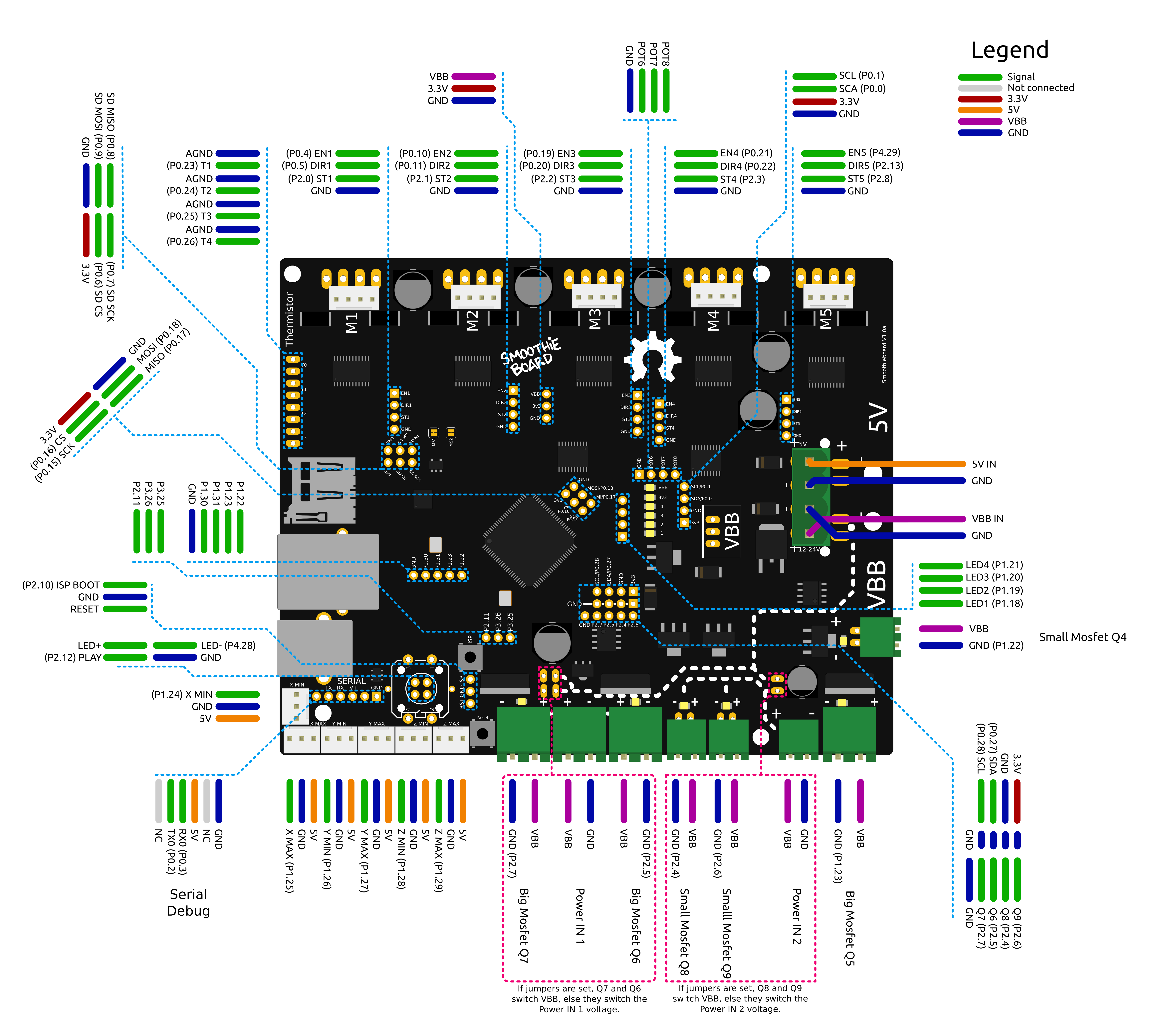
Smoothieboard wiring diagram - click to enlarge
Pin Capabilities
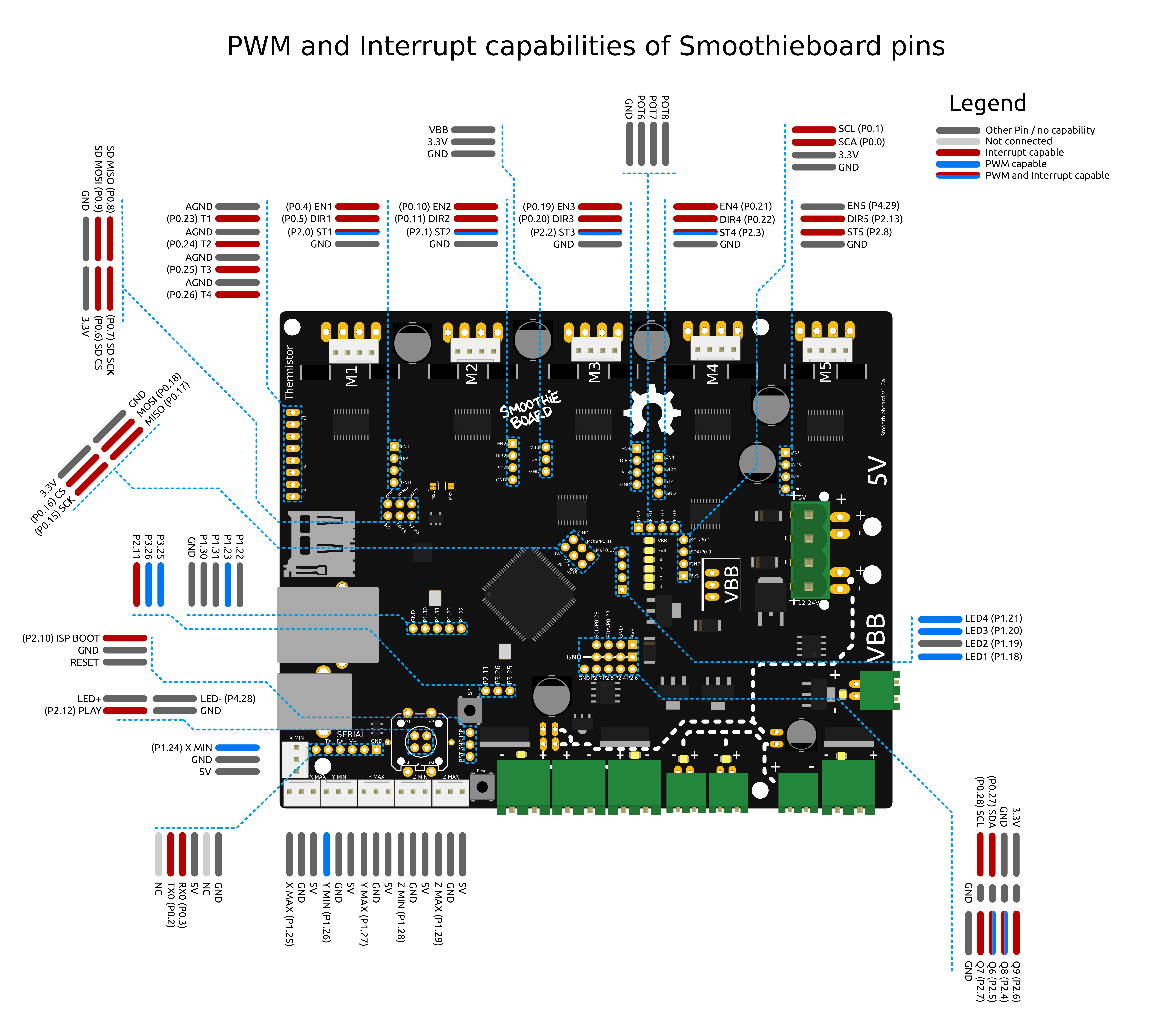
Smoothieboard pin capabilities - click to enlarge
View full size pin capabilities diagram
Also see the pin usage table for detailed information about each pin.
The V2 pinout diagrams are still being created. Check back soon for updated wiring and pin capability diagrams for V2 boards.
Important Notes
Protecting a power input with a fuse
Fuse Protection
A Fuse is a device which sacrifices itself (gets destroyed and stops letting electricity through) if the current passing through it is higher than a certain value.
As such, adding a fuse between your power supply and a power input on your Smoothieboard protects you against short circuits, overloading, mismatched loads, or any kind of device failure.
You need to choose a fuse with a value higher than your “normal” current for a given circuit.
For example, if your heated bed consumes 10A, you want to have a 15A fuse protecting it, that way if everything is fine the fuse does not burn, but in case of a short circuit, it does.
Example Fuse Installation
Here is an example of a fuse protecting the mosfet power input:
Note: The fuse must have an adequate current rating for your application
Troubleshooting a problem with your Smoothieboard
If you have a problem with your Smoothieboard, don’t panic.
First of all, make sure you have read the documentation on this website, it is likely the information you are looking for is here, it is a very complete documentation. In particular take a look at:
If you can’t find your answer here, you can also ask for help in the community. There are many channels:
And of course try to find the answer to your question on this page too.
Below is the list of the most common problems and things you can try to solve them :
Table of contents
How to troubleshoot
Here are some of the things you should do when running into trouble, and before asking any kind of help around :
1. Backup your configuration file
Take your SD card out, and save your configuration file to your computer. If you are going to be messing around with the printer, you’d better be safe and make sure if anything happens to your SD card, you will not lose the work you put into your configuration file.
You should really have done this already, it’s just good sense.
2. Clean your SD card
Sometimes SD cards get corrupted, and it can cause all sorts of weird and difficult to understand problems.
You should :
- Format your SD card ( as FAT32 )
- Paste the most recent firmware file on your SD card
- Paste your configuration file to the SD card
- Insert the SD card back into the board and reset it
Then see if your problem still exists or not.
It’s probably a good idea to do this even if you don’t think it’s a SD card related problem, quite often people think it’s not and it fixes the issue anyway.
Config Override Warning
What is Config Override?
The config-override file is a special file that Smoothie uses to store settings that should take precedence over your main configuration file.
This is particularly useful when you want to save calibration values or other settings that shouldn’t be in your main config file.
Enabling Config Override
In Smoothieware V1, the config-override file is automatically active if it exists on your SD card. You do not need to enable it—if the file is present, it will override settings from your main config file.
In Smoothieware V2, config-override functionality must be explicitly enabled by adding this setting to your config.ini:
[general]
config-override = true
Without this setting, any existing config-override.ini file will be ignored, and only your main config file will be used.
How to Check for Override Issues
If your configuration changes aren’t taking effect:
- Check if you have a
config-overridefile on your SD card (no extension) - If it exists, the override is automatically active—it will be loaded on every boot
- Review its contents to see what settings are being overridden
- Either modify the override file or temporarily remove it for testing
- Remember to save a backup before removing any files
- First check if
general.config-overrideis set totruein your[general]section—iffalseor missing, config-override is disabled - If enabled, check if you have a
config-override.inifile on your SD card - Review its contents to see what settings are being overridden
- Either modify the override file or temporarily disable it by setting
config-override = false - Remember to save a backup before removing any files
When to Use Config Override
Config override is most useful for:
- Storing calibration values that you’ve dialed in
- Keeping machine-specific settings separate from your main config
- Allowing
M500 command to save settings without editing the main config file
Best Practices
- Document what settings you’ve saved to config-override
- Keep a backup of your override file
- When troubleshooting, temporarily remove the config-override file to isolate issues
- Consider whether a setting should be in main config or override
- When troubleshooting, set
config-override = falseto disable override without deleting the file (just change it back totruewhen done) - When migrating from V1, remember to add
config-override = trueto your[general]section if you want this feature enabled - Consider whether a setting should be in main config or override
3. Incremental wiring
This may not apply to your specific problem, but if it does :
Unplug everything from your board, then plug things back into the board one at a time, resetting the board and testing your problem each time you do.
Start with USB, then the power supply, then do the same for each peripheral in turn until everything is plugged back in. If you do not know what the problem is, it should help you pinpoint it.
4. Prepare your config for asking for help.
Open your configuration file.
Copy its content.
Now go on the pastebin.com website.
Paste your configuration file’s content into the « New paste » box
Click on « Create new paste »
The website will give you a link. You can now give this link to people on IRC or the forums, without having to copy/paste the entire file, and people will be able to see your config and help you.
5. Isolate the problem as much as possible
You want to make sure your remove as many influencing factors when debugging an issue. This makes sure you don’t confuse a problem with another, or miss the fact that two problems are actually working together to ruin your life.
For example, let’s say your ethernet is not working, then you want to do a few things :
- Unplug everything from the board except USB ( which you need for power ) and Ethernet. This makes sure the problem isn’t coming from some of the rest of the wiring
- Use the latest version of the edge firmware ( see Getting Smoothie ). This makes sure people helping you have the same frame of reference as you
- Use the latest version of the example config file ( see Configuring Smoothie ), and strictly only modify the lines related to Ethernet, leave all the rest unchanged. This makes sure the rest of your config isn’t part of the problem
- Try at least two different Ethernet cables, this makes sure the problem isn’t the cable
- Try at least two different routers/networks, this makes sure the problem isn’t the network
Of course, this is for network problems, adapt depending on your exact case. Use your smarts.
Make sure this is not a hardware problem before asking for help also, is your laser mirror path well aligned? Are all your screws tightened? Is your machine rigid enough for the task? Is your belt tight? Etc.
Finally, make sure you mention all those steps you have taken when asking the community for help, if you don’t people will start telling you to do things you have already done.
6. Describe/Take a picture of your setup
Take a picture of your Smoothieboard, a global view of it ( tip : pictures are much sharper and therefore useful, if neither the camera nor the subject are moving. Deposit your camera on a flat surface or fix it in some fashion. If you think pressing the button will make it move, remember you can use a 5-second countdown to take pictures. )
Also take pictures of the connectors, wiring, motors, and overall machine. A picture is worth a thousand words.
When posting on a forum/social media to get help, attach your config ( it’s pastebin link ), but also these pictures, as well as a description of your machine/setup ( as detailed as you can be patient for, with special time taken for anything that is not commonly done/unusual ).
If using a mailing list, do not insert the pictures in the body of your email, but rather attach them to the email. This make things easier for volunteers helping you, and not doing so often leads to ridiculously weird email client layouts ( for example if the picture is much larger than the screen ).
7. Before asking the community for help.
If you have an Open-Source board like the Smoothieboard, a board from Panucatt, or one of the many designed by the community and that support the project, ignore this.
If you chose to buy a closed-source derivative board, however, please understand that those are considered to be toxic to the project, and that asking the community for help with those would be similar to asking the community to help with destroying itself.
Please ask for help from the person that sold you that board, before asking the community for help. Providing support for their product is the absolute very least they can do. And of course unsurprisingly they are well known for not doing even that. But please ask them first.
If they don’t help you, then feel free to ask the community, but please be aware even then some won’t accept to help. If this happens please remember that the community helping you is a service they are giving you, and that when they choose not to, they are only not doing you a favor.
Always make sure you have your board updated to the very latest version of the firmware before you ask for help.
You will likely be asked to provide the result of the version command so make sure to prepare that in advance.
Ideally, use Pronterface when troubleshooting, for various reasons ( one of which is that some hosts hide error messages. Another one is it helps us be better at helping you if everybody we help has the same host ).
1000% make sure you use the very latest example config file ( with your values ported over to it ), and the very latest firmware versions. This can’t be repeated enough. This is said here and everywhere many times. If you come in asking for help, and after an hour everyone realizes your firmware is a year old, there is going to be a lot of frustration at you, you probably want to avoid that if you can.
Power supply problems
Smoothieboard does not work at all
First off, do any LEDs turn on on the board when plugged in via USB ?
If not, that’s very bad, contact your seller.
If LEDs turn on, it then depends on what they do :
There is a series of LEDs on your board, near the center.
They are labelled VBB ( red ), 3.3V ( orange ), and 1 2 3 and 4 ( all green ).
We are still only interested in the green LEDs.
Different behavior can represent different situations and problems for the board :
 Then the firmware is running, and the LEDs are displaying correct behavior.
 Then the firmware is running, but the board encountered a problem reading or accessing the SD card, or the configuration file on the SD card.
Try taking the card in and out of the board several times, or try using another SD card ( here is how to set up a new card ).
See below for more details.
 Or this : Then the firmware is not running.
You can try flashing the firmware again.
See below for more details.
Plugged in and 3.3V LED is OFF
This means the microcontroller on your Smoothieboard is not getting any power.
Smoothieboard gets this power from your USB cable (unless you are using the optional voltage regulator or the 5V input): check that Smoothieboard is correctly connected to a USB port or otherwise powered.
If it is, but the 3.3V LED is still not lit up, one other possible reason would be a short on your board.
Unplug the USB cable, and disconnect everything else from your Smoothieboard. Then plug the USB cable back in and check if it starts working again.
If so, there is a short in one of the peripherals. Quite often this is due to incorrectly wired Endstops (shorting 3.3V to GND instead of connecting GND to Signal for example).
If this still does not solve the problem, examine the board for problems with your soldering of components/connectors and any other anomalies you can detect.
If you can still not find anything, contact the community.
The 3.3V LED is ON but LED4 is not ON
LED4 indicates SD card status. If it is not lit up, it means there is a problem with your SD card.
First thing to try is taking the microSD card out of your Smoothieboard and testing it on your computer with a SD card reader.
If it works there, copy the files that are on it elsewhere, format it (as FAT32), copy the files back on it and try again.
If it still does not work in the Smoothieboard after this, take another microSD card, format it (as FAT32), copy the files to it, then try again.
If it still fails, then as you tried two SD cards they are probably both fine. The problem could be with the files on it.
Format a SD card as FAT32, and on that fresh card, copy two files:
- firmware.bin , with this exact name, which you can find here
- config , with this exact name, which you can find here
Then insert the card into your Smoothieboard and try again.
The 3.3V LED is ON but none of the 1 through 4 LEDS is ON
Or LED1 and LED4 are ON, but LED2 and LED3 are not blinking.
This could be caused by a firmware bug, or by a problem with your configuration file.
Try with a fresh configuration file, and if it does not solve the problem contact the community.
If you soldered the smoothieboard then check either the 12 MHz oscillator or the SD card/SD card slot. *This could be a bad solder joint with the 12 MHz oscillator (crystal), a bad SD card slot, a bad SD card, and/or a bad config file.
The 3.3V LED is ON, and LEDs 1 and 3 are ON and 3 is not blinking, LEDs 2 and 4 are OFF
This could mean your board has no bootloader, which is very wrong. Contact whomever sold you your Smoothieboard.
The 3.3V LED is ON, and LEDs 1, 2, 3 and 4 are ON and none are blinking
This could mean you have a bootloader but no firmware was ever flashed or found on the SD card. Again, this is very wrong, contact whomever sold you your Smoothieboard.
12 or 24V power is plugged in but the VBB LED is not ON
Unplug power immediately !
Check that your power is not in reverse polarity.
Even if you think you have it correct (read the instructions carefully, the markings on the board can be a bit confusing), try reversing it just in case.
All LEDs are on but LED 2 and 3 are solid
Firmware didn’t get flashed, you need to flash it and also make sure you uploaded a valid config.
It smells like something is burning!
Whaaaaa! Unplug everything! Get a fire extinguisher!
Now, try to remember exactly what you were doing with your board, and contact whomever sold it to you.
Mosfets are never turning on
You configured everything right and plugged the heating elements into your mosfet outputs, but no matter what you do, they do not turn on.
Note Smoothieboard does not have a single power input. It has one for the motors, and then the big mosfets have their own inputs, and the small ones have theirs. You need to provide power to each, according to the mosfets you are using. See the documentation on this, it goes into great detail and has diagrams.
Grounding problems
If you don’t know about grounding, it’s a great idea to read this post : Earth, Ground, and the Grid
Configuration problems
Changes to configuration are ignored in general
The config changes are not taken into account, files do not appear or do not update on the SD card
If anything like this happens, that could be related to the SD card “messing up”, format the SD card ( as VFAT/FAT32 ), then paste your files back on it.
See SD card.
Sometimes the SD card can get corrupted after which it will do strange things. Always make sure you unmount ( virtually not physically ) your SD card after doing anything on it
For configuration changes which are being made in the config file and are not being applied, check that they are not being overridden in the config-override file in the same folder (see the “What is Config Override?” section earlier on this page for full details).
Changes to configuration are ignored on a particular line
If a line begins with the # character, it means it is “commented out” and Smoothieboard will ignore it.
You need to remove the # character and Smoothie will now take the line into account.
« No strategy found to handle G32 »
If you try to run bed leveling or calibration, and the board answers something like « No strategy found to handle
- Flash the very latest firmware
- Start your configuration fresh from the very latest example configuration file
- Enable the calibration strategy by following the exact instructions at zprobe
This error message most of the time means your config and firmware aren’t up to date with each other. Upgrading everything solves the issue.
Bed leveling seems to have no effect
If you try to run bed leveling or calibration, and it seems to have no effect at all, please do the following :
- Flash the very latest firmware
- Start your configuration fresh from the very latest example configuration file
- Enable the calibration strategy by following the exact instructions at zprobe
This symptom most of the time means your config and firmware aren’t up to date with each other. Upgrading everything solves the issue.
Web Interface problems
Why is my web interface missing?
If you connected to your Smoothieboard over the network and expected to see the web interface but it wasn’t available, see the Missing Web Interface page for complete instructions on how to install it on your SD card.
Movement problems
My stepper motor does not turn correctly
If it always turns in the same direction, and/or turns only weakly, and/or makes a strange sound, one very common cause of that is that only 3 of the wires of the motor are connected to the stepper motor driver.
Check your connector and your cables.
If that doesn’t help, do the following :
- Try this motor on another stepper motor driver
- Try another motor on this stepper motor driver
My stepper motor does not turn at all and makes a very high-pitched sound
A motor not moving at all, or moving erratically, or making a high pitch sound, or vibrating instead of moving, is a typical consequence of trying to move a motor too fast, or trying to accelerate a motor to too high a speed with too high acceleration (not “giving it enough time” to reach its target speed).
This can happen most often with Z axis (or any leadscrew driven stepper motor) due to the high steps per millimeter number, but also sometimes with other types of axes/systems, if you are trying to move it too fast.
Try asking it to move at a much lower speed ( for example G0 Z100 F100 ).
It’s also possible you are trying to home, or to probe too fast. See the corresponding modules for how to modify the default speeds.
If you are using external stepper motor drivers (driven by ENn, Stn and DIRn pins) check polarity, voltage and timings of signals to your driver. Also consider increasing
My stepper motor does not turn at all
And it does not present any resistance/torque when turning it manually :
This means the stepper motor driver is maybe not able to power the stepper motor.
Try wiring a different motor to that driver and try again. If the new motor works on this driver, then the motor is the problem. Otherwise the driver is probably the problem.
If you changed any of the stepper