Basics
The Spindle is the main effector on your CNC Mill/Router.
It holds the end mill or drill bit, makes it turn and remove material.
While manual control is sometimes fine (turn it on before starting your G-code, off when you are done), it is so much neater to have G-codes to control it automatically.
Simply put an ON G-code at the beginning of your G-code file, and an off G-code at the end of your G-code file, and you don’t have to think about it anymore.
The spindle module supports different types of spindles which are described in the following subsections.
General
The spindle module has an option which lets you enable or disable the entire module:
V1 Configuration (flat namespace):
spindle.enable                                   true   # set this to false to disable the spindle module
spindle.ignore_on_halt                           false  # set to false to turn off spindle during HALT (safe, recommended)
                                                        # set to true to keep spindle running during emergency stop/limit hit (use with extreme caution)
V2 Configuration (INI sections):
[spindle]
enable = true                # set this to false to disable the spindle module
ignore_on_halt = false       # set to false to turn off spindle during HALT (safe, recommended)
                             # set to true to keep spindle running during emergency stop/limit hit (use with extreme caution)
G-code
Available G-code commands:
M3 will start the spindle.M3 S5000 will start the spindle and set speed to 5000 RPM.M5 will stop the spindle. Last set RPM is remembered and used for nextM3 command ifS argument is not given.M957 will report the current spindle speed and PWM value. This returns not the actual value but the value that was set throughM3 .M958 will report the current PID parameters.M958 Px.xxx Ix.xxx Dx.xxx will set them (to save the new values, you need to edit config file manually).
PWM Spindle
It needs a feedback sensor to adjust the speed using a PID control.
Example config options
V1 Configuration (flat namespace):
spindle.type                                 pwm               # sets the spindle module to PWM mode
spindle.pwm_pin                              2.5               # Big Mosfet Q7. Pin must be hardware PWM capable.
spindle.pwm_period                           1000              # default 1000, sets the PWM frequency
spindle.max_pwm                              1.0               # maximum PWM duty cycle (0.0 to 1.0)
                                                               # limits power to protect motor from overcurrent
                                                               # set lower if motor runs too hot at full power
spindle.feedback_pin                         2.7               # Pin must be interrupt capable.
spindle.pulses_per_rev                       1.0               # default 1. Defines the number of pulses occur for each rotation
spindle.default_rpm                          5000              # default 5000. Defines a default RPM value in case no RPM value is provided.
spindle.control_P                            0.1               # default 0.0001. P value for the PID controller
spindle.control_I                            0.1               # default 0.0001. I value for the PID controller
spindle.control_D                            0.1               # default 0.0001. D value for the PID controller
spindle.control_smoothing                    0.1               # default 0.1. This value is low pass filter time constant in seconds.
V2 Configuration (INI sections):
[spindle]
type = pwm                   # sets the spindle module to PWM mode
pwm_pin = 2.5                # Big Mosfet Q7. Pin must be hardware PWM capable.
pwm_period = 1000            # default 1000, sets the PWM frequency
max_pwm = 1.0                # maximum PWM duty cycle (0.0 to 1.0)
                             # limits power to protect motor from overcurrent
                             # set lower if motor runs too hot at full power
feedback_pin = 2.7           # Pin must be interrupt capable.
pulses_per_rev = 1.0         # default 1. Defines the number of pulses occur for each rotation
default_rpm = 5000           # default 5000. Defines a default RPM value in case no RPM value is provided.
control_P = 0.1              # default 0.0001. P value for the PID controller
control_I = 0.1              # default 0.0001. I value for the PID controller
control_D = 0.1              # default 0.0001. D value for the PID controller
control_smoothing = 0.1      # default 0.1. This value is low pass filter time constant in seconds.
Since I'm experimenting with hobby ESC+motor combos (1:8 scale 3 phase 4068 like motor) I wanted to share its config.
ESCs act like hobby servos - 20 ms period time, 1.5-2ms duty cycle time - so instead of having modified the spindle code, I've created a switch for commands
Due to the very small duty cycle window, you won't have much control over the motor: S7.5 is neutral, S12.5 is "fastest" after calibrating the ESC manually with bCNC (read ESC's manual; below S7.5 is braking for now).
The following code is working, setting neutral upon boot - ESC init:
V1 Configuration (flat namespace):
switch.servo.enable                          true
switch.servo.input_on_command                M3
switch.servo.input_off_command               M5
switch.servo.output_pin                      1.23o!
switch.servo.output_type                     hwpwm
switch.servo.startup_state                   true
switch.servo.startup_value                   7.5
switch.servo.default_on_value                7.5
switch.servo.failsafe_set_to                 0
V2 Configuration (INI sections):
[switch]
servo.enable = true
servo.input_on_command = M3
servo.input_off_command = M5
servo.output_pin = 1.23o!
servo.output_type = hwpwm
servo.startup_state = true
servo.startup_value = 7.5
servo.default_on_value = 7.5
servo.failsafe_set_to = 0
Analog Spindle
This module is used to control a VFD with a PWM that is converted to a 0-10V analog signal by an additional circuit.
That circuit also provides an optocoupler for switching the VFD RUN signal.
It is also the mode of choice if you run a brushless motor spindle driven by an ESC, in that case, you will not need any additional circuitry.
The downside is that the signal is not completely linear and may be interfered with by noise.
If you can use a VFD that supports Modbus/RS485, it's highly recommended to use that technique!
Example config options
V1 Configuration (flat namespace):
spindle.type                                     analog   # set the spindle type to analog, can also be used for ESC spindles controlled by a PWM
spindle.max_rpm                                  24000    # set the max spindle speed that is achieved at 100% PWM
spindle.min_rpm                                  100      # minimum spindle speed in RPM
                                                          # prevents unstable low-speed operation
                                                          # RPM below this (but > 0) are clamped to min_rpm
                                                          # M5 or S0 still turns spindle completely off
spindle.pwm_pin                                  2.4      # the pin which emits the PWM signal
spindle.pwm_period                               1000     # the PWM frequency
spindle.switch_on_pin                            2.6      # the pin which is used to enable the VFD (optional)
V2 Configuration (INI sections):
[spindle]
type = analog                # set the spindle type to analog, can also be used for ESC spindles controlled by a PWM
max_rpm = 24000              # set the max spindle speed that is achieved at 100% PWM
min_rpm = 100                # minimum spindle speed in RPM
                             # prevents unstable low-speed operation
                             # RPM below this (but > 0) are clamped to min_rpm
                             # M5 or S0 still turns spindle completely off
pwm_pin = 2.4                # the pin which emits the PWM signal
pwm_period = 1000            # the PWM frequency
switch_on_pin = 2.6          # the pin which is used to enable the VFD (optional)
PWM to analog converter circuit
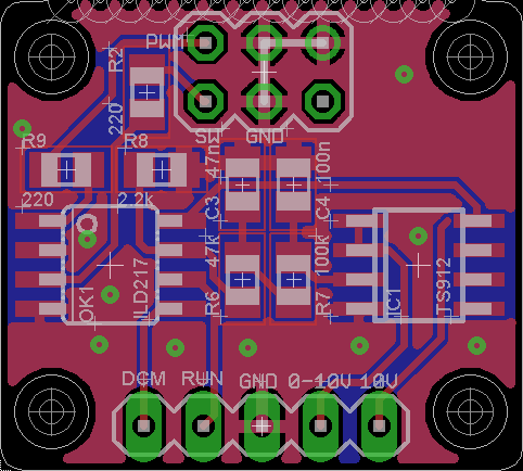
VFD adapter board PCB - Used to talk to your VFD via an analog signal
This is an example of a small extension PCB that contains a circuit to convert the 3.3V PWM signal into a 0-10V analog signal.
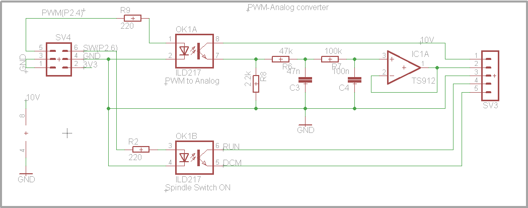
VFD adapter board schematic - For the curious
This is the related circuit diagram for the converter.
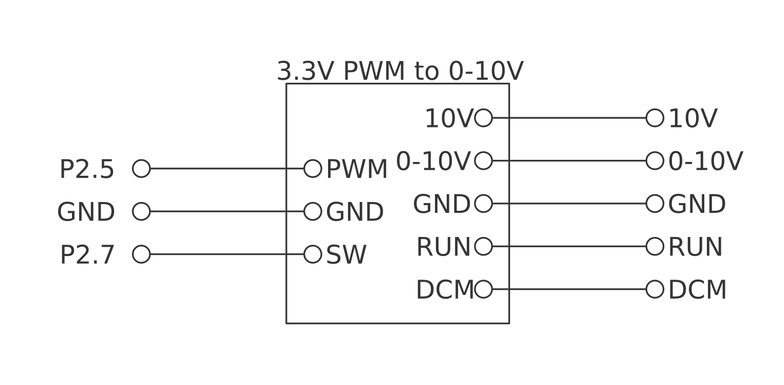
VFD adapter board wiring - How to connect it to your Smoothieboard and VFD
This example shows how to wire the Smoothieboard to a Huanyang VFD using the PCB shown above.
As you can see in the graph, the signal is better at the beginning and at the end.
Modbus Spindle
This module is used to control a VFD using an RS485 communication bus.
It provides a Modbus implementation and is easily extendable to support a wide range of Modbus compliant VFDs.
But it also can support VFDs that are not compliant with the Modbus standard such as the widely used Huanyang VFD that is popular and cheap on eBay.
At the time of writing only the Huanyang is implemented, but it is very easy to extend the module for many other models.
Example config options
V1 Configuration (flat namespace):
spindle.type                                     modbus   # set the spindle type to modbus/RS485
spindle.vfd_type                                 huanyang # set the VFD type, this is necessary because each inverter uses its own commands
spindle.rx_pin                                   2.6      # RX pin for the soft serial
spindle.tx_pin                                   2.4      # TX pin for the soft serial
spindle.dir_pin                                  2.5      # RS485 is only half-duplex, so we need a pin to switch between sending and receiving
V2 Configuration (INI sections):
[spindle]
type = modbus                # set the spindle type to modbus/RS485
vfd_type = huanyang          # set the VFD type, this is necessary because each inverter uses its own commands
rx_pin = 2.6                 # RX pin for the soft serial
tx_pin = 2.4                 # TX pin for the soft serial
dir_pin = 2.5                # RS485 is only half-duplex, so we need a pin to switch between sending and receiving
Huanyang VFD Modbus Parameters
In order to get the Huanyang VFD accepting commands via ModBus, you need to change a few parameters:
- PD001: 2 (Source of run commands: communication port)
- PD002: 2 (Source of operating frequency: communication port)
- PD163: 1 (Communication address: 1)
- PD164: 1 (Communication Baud Rate: 9600)
- PD165: 3 (Communication Data Method: 8N1 RTU)
RS485 extension board
Like an analog spindle, the Modbus spindle needs an external circuit, but that is much simpler.
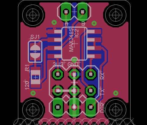
VFD Modbus signal adapter PCB - Used to talk to your spindle over RS485 differential signals
This is an example of a small extension PCB that contains a circuit to convert the 3.3V UART signal into an RS485 signal.
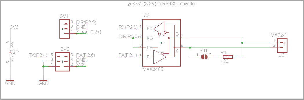
VFD Modbus signal adapter schematic - For the curious
This is the related circuit diagram for the converter.
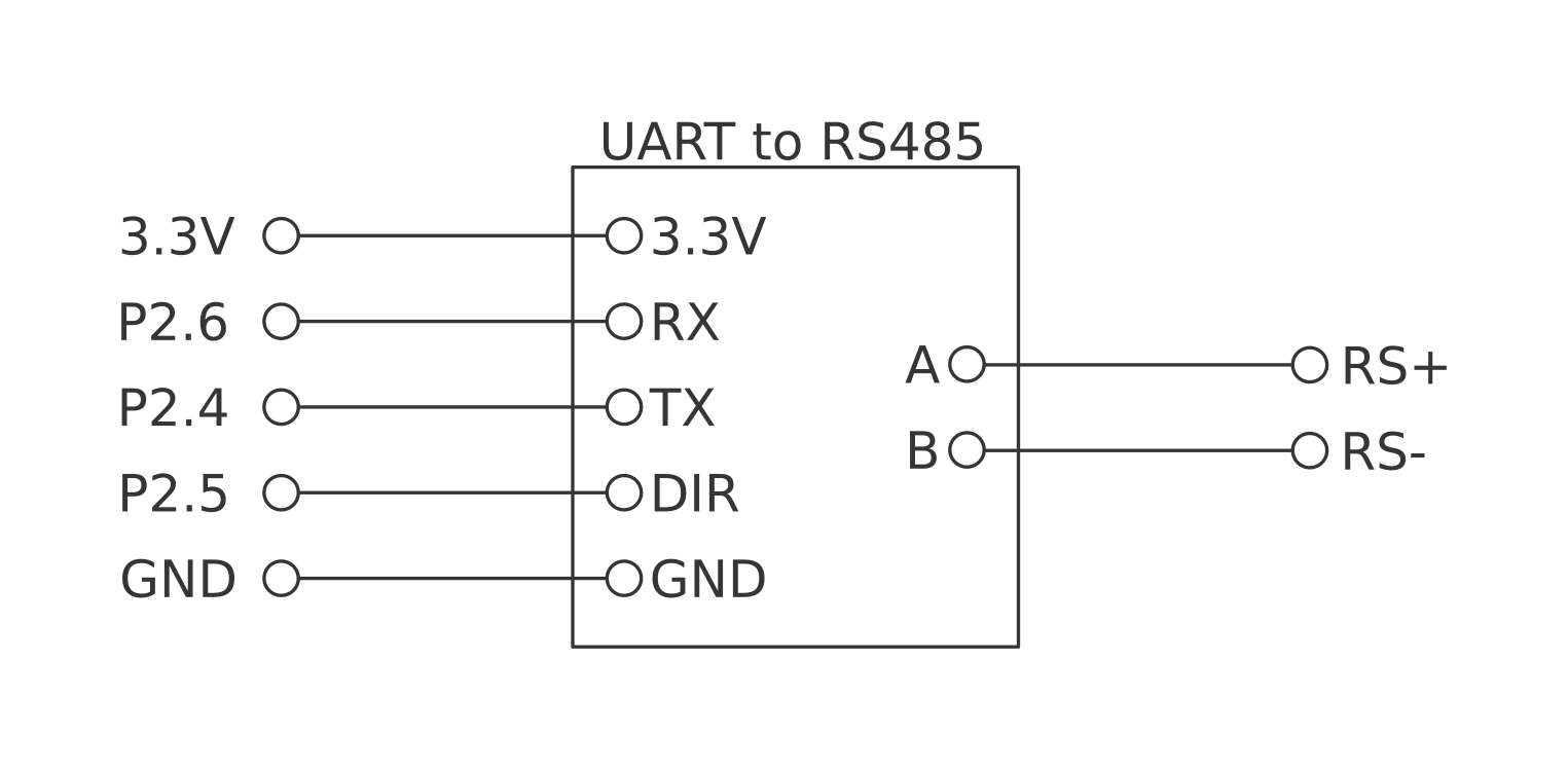
VFD Modbus wiring - How to connect it to the Smoothieboard and the VFD
This example shows how to wire the Smoothieboard to a Huanyang VFD using the PCB shown above.