ROS and Smoothie
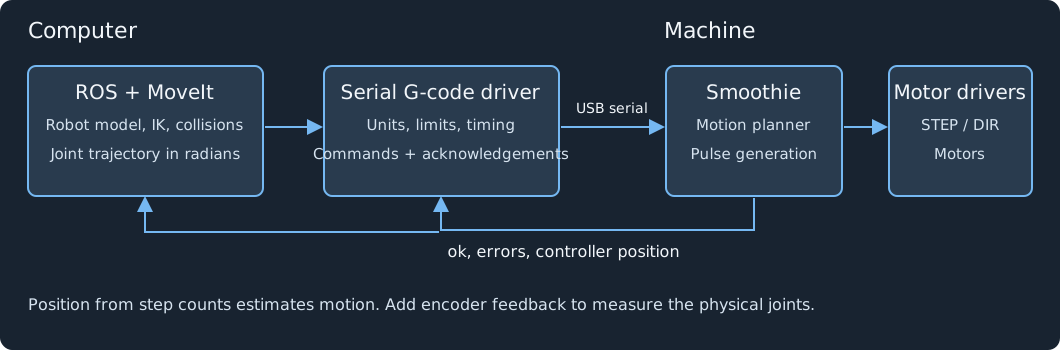
You can use Smoothie to drive the motors of a robot that you control from ROS. Run ROS on a computer, connect that computer to Smoothie’s USB serial port, and send G-code through a driver that converts your robot commands into motor coordinates.
ROS, the Robot Operating System, provides software for robot models, sensors, visualization, planning, and communication between programs. Smoothie handles acceleration and step generation on the board. For an arm, you can use MoveIt to calculate joint angles and check the planned path against the robot’s collision model.
This page covers a Cartesian machine and an arm with three independent rotary joints. It includes a small ROS 2 command example and a configuration outline for MoveIt. The example needs calibration for your machine. The projects below publish source for several control paths, including a historical Smoothie CNC interface. Check each project’s firmware and ROS version before adapting its driver.
Start with these projects
These projects show several ways to connect ROS to a G-code controller. The distinction between planning a path and executing it matters when choosing code to reuse.
| Project | Connection and ROS version | Useful material |
|---|---|---|
| PARA | Smoothieboard arm; supplied Python controller uses PyBullet. The authors discuss using its URDF with ROS. | Three-joint arm geometry, URDF and meshes, host-side angle conversion, Smoothie connection. |
| cnc_interface | ROS 1 Cartesian CNC interface with an explicit Shapeoko/Smoothieboard launch example. | ROS callbacks, serial transport, launch parameters, position/status reporting; review its startup and stop behaviour below. |
| Thor-ROS | ROS 2 Humble, MoveIt 2, ros2_control; serial G-code to modified GRBL or RepRapFirmware. | Hardware interface, robot description, controller configuration, coupled wrist mapping. |
| grbl_ros | ROS 2 CNC driver; serial GRBL status and command/file actions. Its README lists older ROS 2 distributions. | Serial transport, machine configuration, G-code actions, coordinate reporting. |
| G-ARM and official source | ROS 2 Humble and MoveIt 2; Python serial commands to GRBL. | Joint-to-motor mapping, URDF, GRBL configuration, educational arm example. |
| uArm Swift Pro | ROS 1 Kinetic; manufacturer ROS nodes send Cartesian G-code to Marlin-derived firmware. | Example of firmware-side kinematics, MoveIt adapter, gripper and pump commands. |
| 3D printing with Moveo | ROS Melodic converts Cartesian print G-code into joint coordinates for modified Marlin. The documented execution uses an SD card. | Offline inverse kinematics, robot description, printing workflow. |
For a Smoothie arm driver, start by reading Thor’s hardware interface. Its serial commands and motor coupling belong to Thor. Change those parts for your arm and verify acknowledgement handling before running it. For a Cartesian machine, grbl_ros’s device code provides a smaller starting point.
Projects that use rosserial and AccelStepper, including moveo_ros and Arctos’s ROS package, use a different hardware protocol. Their URDFs may help you describe an arm, but their step messages do not establish a G-code connection to Smoothie. Arctos also has a separate staged G-code path in its GUI; keep those implementations distinct when reading its repositories.
A historical ROS interface for Smoothie CNC machines
The MIT-licensed cnc_interface includes a Smoothie/Shapeoko launch file, a ROS node, and a serial controller class. It derives from ROS-GRBL. This is a direct Smoothie-specific source to study, although its ROS 1/Python 2 interface needs work for a new ROS 2 driver.
The launch example sets port to /dev/ttyACM0 and baudrate to 115200. It also supplies travel limits, speeds, and steps/mm to the Python class; those parameters do not program the board’s firmware configuration. Set and verify the actual board configuration yourself.
Its movement callback treats Twist.linear.x, .y, and .z as target coordinates in millimetres. That is this project’s convention: standard ROS Twist describes velocity. Use an explicit position/trajectory interface in a new driver. Its position parser expects both GRBL-style MPos and WPos fields and selects work coordinates, so verify the installed Smoothie build’s status response before reusing it.
Read the startup and stop code before launching it on hardware. The controller class sends G90, $H to home, and G92 to set the origin at startup. Its stop path sends M18, which disables motors; that does not establish a safe abort or support a gravity-loaded joint. Its move function reads an acknowledgement without providing an M400 completion barrier. Treat this code as a historical porting reference, not an unchanged arm driver.
Other control paths worth studying
G-Arm’s current driver.py consumes joint_states and passes angles through its robot mapping to the GRBL serial library. In your driver, keep target commands separate from /joint_states, which reports robot state. Echoing a visualization’s state into a motor command does not supply trajectory cancellation, timing, or measured feedback.
For RepRapFirmware calibration, Thor publishes Fly Super8 Pro configuration files. The separate ThorRR fork and Bifrost document another RRF board and control application. Use their actuator mapping and homing structure as references; verify a ROS connection for the same board, firmware, and driver instead of transferring a fork’s test claims to Thor-ROS.
Arctos’s rosjog.py reads ROS joint states, converts angles and wrist coupling, and writes a jog.tap file; sendgcode.py sends that file over serial. This demonstrates a staged conversion path. Its jog representation omits an explicit G0/G1, so do not send that output to stock Smoothie unchanged or treat it as timed trajectory streaming.
The OpenLH paper adds a fabrication example using uArm’s Marlin-derived firmware and serial G-code. Its authors used Python and mention an available ROS interface. The vendor’s ROS source establishes that interface; the OpenLH experiments themselves do not demonstrate ROS execution.
For printing with an arm, distinguish the motor controller from the tool controller. CRM sends arm motion through MoveIt and the UR3 driver, while a Duet board receives extrusion and heating commands over HTTP. Yao et al. similarly coordinate a UR3 with Marlin-controlled extrusion; Xu et al. divide motion between a UR5 and a Marlin-controlled XY table. These are useful coordination examples, but they do not show a printer board driving the articulated joints.
There are also promising builder reports and vendor drivers. A six-joint Marlin builder reports ROS 2 and MoveIt 2 control and publishes a firmware fork; a complete ROS bridge was not established in this source review. WLKATA’s ROS 2 package advertises serial G-code control, but its firmware distribution is proprietary. Neither supplies an existing Smoothie driver.
PARA: an arm controlled by Smoothie
Albert Tai and colleagues built PARA around a Smoothieboard and external motor drives. They provide an arm description and a Python example that calculates motor angles with PyBullet, converts the angles to G-code, and sends the commands to Smoothie. Their design repository includes the robot model and mechanical files.
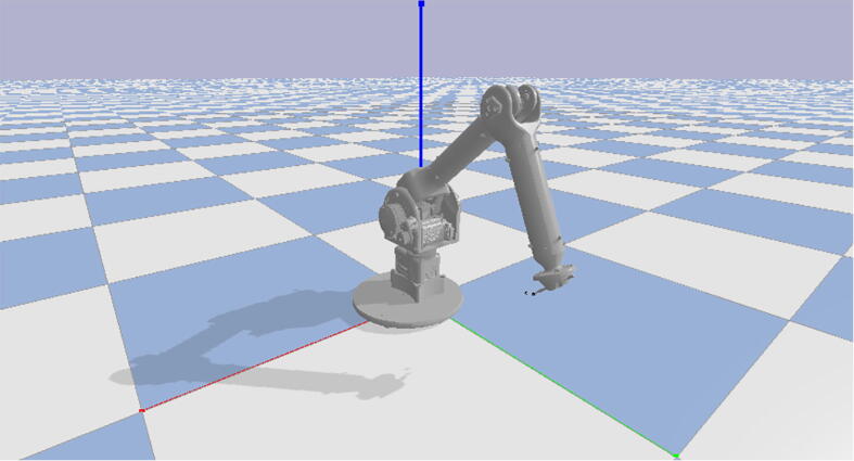
Figure 21 from Tai et al., PARA: A one-meter reach, two-kg payload, three-DoF open source robotic arm with customizable end effector, HardwareX, 2021. Reproduced unchanged under CC BY 4.0. The screenshot shows PyBullet, not ROS.
Use PARA as evidence for the Smoothie motor-control path. You still need a ROS driver to connect its model to ROS execution. Also check commands against your firmware: the paper lists M584, a RepRapFirmware motor-mapping command, which is not a stock Smoothie axis-configuration recipe.
The authors also publish Config.txt, PARA_CartesianControlsDemo.py, and the URDF/mesh archive. In that configuration, alpha, beta, and gamma each use 80 steps per numerical coordinate unit. Their Python mapping uses a ratio of 2.717, couples the shoulder into the elbow motor, and converts motor radians into numerical coordinates using angle / 6.283 × 80.
Keep that conversion and the original drive setup together when studying PARA. Those numbers do not mean 80 steps per joint degree, and PARA’s coupled mechanism differs from the independent-joint example below. Its full configuration also enables printer-related modules; do not install it on a different arm as a ready-made configuration. The OSF download includes an MIT license, copyright Albert Tai, 2020; preserve it when reusing the supplied files and check notices for incorporated third-party code.
Choose where to calculate the kinematics
Kinematics describes the relationship between joint positions and the position of the tool. Forward kinematics calculates the tool position from the joints. Inverse kinematics calculates joint positions for a requested tool pose.
For a Cartesian machine, send millimetres to Smoothie. A ROS position of 0.020 m becomes X20 in G-code. Smoothie can also handle a supported arm solution, such as CoreXY or Morgan SCARA. Use that machine’s configuration and send tool coordinates in its expected units.
For an articulated arm with host-side kinematics, calculate joint angles in ROS and send one numerical coordinate per motor. For the three-joint example below, configure Smoothie’s Cartesian arm solution and use X, Y, and Z as motor coordinates. Those values represent joint degrees in this application, even though Smoothie’s configuration calls them millimetres. Smoothie does not know the arm’s link lengths, joint limits, or collision geometry in this arrangement.
Choose one conversion path. If ROS has already converted a tool position to motor angles, sending those angles through Smoothie’s SCARA kinematics would apply another, incorrect conversion.
For six joints, check your board’s outputs, firmware build, configured actuator count, and axis names. Extra actuators and extruders require separate configuration. Thor’s X Y Z U V W RepRapFirmware mapping and its modified-GRBL mapping do not describe Smoothie’s extra axes. See motion control and the supported G-codes for your firmware.
Configure the board
Begin with a working configuration for your board and motor drivers. Set motor current, wiring, enable polarity, and homing before introducing ROS. Keep a physical emergency stop within reach, and support joints that can fall when you disable a motor.
For the joint-degree configuration, disable inherited bed/grid leveling and other printer compensation. Remove any startup sequence that reloads those transforms. Selecting Cartesian kinematics or using G53 does not disable compensation; an active transform can change your motor targets.
The following calibration example assumes a 200-step motor, 16 microsteps per full step, and a 10:1 reduction between each motor and its joint:
steps per joint degree = 200 × 16 × 10 / 360 = 88.888889
For these independent joints, one firmware coordinate unit represents one joint degree. A target of X10 moves the first joint ten degrees from its machine-coordinate zero. Set the physical driver’s microstepping to match the calculation. An external drive that interprets STEP/DIR through electronic gearing needs its own pulses-per-joint-degree calculation.
Smoothieware V1
Merge these settings into your existing config file. Keep your board’s pin assignments and current settings:
arm_solution                 cartesian
alpha_steps_per_mm           88.888889
beta_steps_per_mm            88.888889
gamma_steps_per_mm           88.888889
alpha_max_rate               60
beta_max_rate                60
gamma_max_rate               60
x_axis_max_speed             60
y_axis_max_speed             60
z_axis_max_speed             60
acceleration                 10
In this example, 60 coordinate units/minute means 60 joint degrees/minute. The acceleration value means 10 joint degrees/s². These are example commissioning values, not limits established for your arm.
Smoothieware V2
Merge these settings into the existing sections of config.ini:
[motion control]
arm_solution = cartesian
default_acceleration = 10
x_axis_max_speed = 60
y_axis_max_speed = 60
z_axis_max_speed = 60

[actuator]
alpha.steps_per_mm = 88.888889
alpha.max_rate = 60
alpha.microsteps = 16
beta.steps_per_mm = 88.888889
beta.max_rate = 60
beta.microsteps = 16
gamma.steps_per_mm = 88.888889
gamma.max_rate = 60
gamma.microsteps = 16
V2 uses the [actuator] section with names such as alpha.steps_per_mm. Check the firmware’s configuration samples for your board. Set the driver’s microsteps separately; copying the numerical calibration does not change an external driver’s switches or electronic gearing.
For a linear machine, use its real steps/mm and millimetre-based speed limits instead. See configuring Smoothie, Cartesian, and external drivers.
Establish the joint zero
Define each joint’s positive direction and physical zero in the URDF and driver configuration. Move or home the arm to a known pose before accepting absolute targets. Verify each joint independently at a small distance, then measure it and correct the calibration.
Check the firmware’s homed state as well as the physical pose. If your build requires homing before motion, configure and complete a safe referencing procedure before using G53. Placing the arm at a known angle by hand does not satisfy that firmware guard.
G92 changes coordinate offsets. It does not find the physical zero or prove that a motor moved. Do not copy a printer’s G28 sequence onto an arm without checking the endstop directions, joint coupling, and the space through which each joint will travel. See endstops.
Use a conversion such as:
motor_coordinate = offset + direction × joint_radians × 180 / π
joint_radians   = direction × (motor_coordinate - offset) × π / 180
Here direction is +1 or -1. The offset places the URDF joint zero at the corresponding firmware machine coordinate. A differential wrist needs a matrix mapping several joint angles to several motors; one scale and offset per joint will not describe it. Thor’s source contains an example of that coupling.
Connect over USB serial
Smoothie accepts text G-code over its USB serial connection. On Linux, identify the board rather than assuming that it is /dev/ttyACM0:
ls -l /dev/serial/by-id/
Use the board’s stable /dev/serial/by-id/... path when available. Grant your account access through the device’s group or a device-specific udev rule. Close Pronterface, serial terminals, and other programs using that port before starting the ROS driver. Give one process ownership of the connection.
The examples use 115200 baud and newline-terminated ASCII. For a physical UART connection, match the firmware’s baud rate and electrical interface; see UART. A USB CDC connection is distinct from that physical UART.
First test commands from a serial terminal. Send each line separately and wait for its acknowledgement:
G21
G90
M114.2
M114.3
G21 selects the millimetre numerical scale and G90 selects absolute positioning. With our rotary mapping, you interpret the resulting coordinate numbers as joint degrees. M114.2 reports the controller’s current machine coordinates; M114.3 reports actuator coordinates. Check those responses against your firmware build before writing a parser.
After establishing the physical zero and confirming clearance, a small first-joint test could be:
G53 G1 X1 F30
M400
M114.3
This requests machine-coordinate X = 1, not a relative one-degree move. G53 bypasses work-coordinate offsets for that move. In this configuration the first joint moves toward one degree, with a path feed of 30 numerical units/minute. Measure the physical motion. Use G1 with an explicit feedrate for these tests, and disable any laser or spindle module that your old machine configuration attached to motion.
Handle the serial protocol
Send a line, wait for ok, then send the next line. Keep a bounded queue and a response deadline. ok does not prove that motion reached the planner or finished: V1 can acknowledge a plain G1 before it processes the move. Continue reading for later faults. Send M400 and wait for its acknowledgement when you need to know that preceding planned moves have finished.
Keep position replies and error messages even when an acknowledgement shares their line. On timeout, disconnect, controller reset, or error, report a fault and stop issuing new motion. A missing acknowledgement leaves you uncertain whether the board accepted the command; reconnecting and replaying it can cause an unexpected move.
Smoothie’s position reports come from its controller state and step counts. They cannot detect a stalled motor, a slipping belt, or a joint that moved while power was off. Publish that limitation with your robot state. Add physical encoders if your application needs measured joint positions.
GRBL drivers may send $H, $X, ?, and $ settings. RepRapFirmware drivers may request M408 JSON. Replace those command and response paths when adapting a driver to Smoothie; sharing the same serial connection and G1 syntax does not make the protocols interchangeable.
Try one target from ROS 2
Install a supported ROS 2 distribution using its installation instructions. This example uses ROS 2 Jazzy on Ubuntu 24.04, Python, rclpy, and PySerial. On that system, install PySerial with sudo apt install python3-serial and source your ROS environment:
source /opt/ros/jazzy/setup.bash
Save the following as smoothie_target.py in your own working directory. It reads a target from ROS parameters, converts radians to our three independent motor coordinates, and prints the G-code. The default is a dry run, with no serial connection.
The narrow ±10° limits, zero offsets, positive directions, and feedrate belong to this demonstration. Replace them with your calibrated limits and mapping before enabling execution. The program sends one target; it does not implement a MoveIt trajectory controller or a robot-state publisher.
import math
import time

import rclpy
from rclpy.node import Node
import serial


def exchange(port, command, deadline_seconds):
    """Send one line and retain its replies until an acknowledgement."""
    port.write((command + "\n").encode("ascii"))
    deadline = time.monotonic() + deadline_seconds
    replies = []
    while time.monotonic() < deadline:
        raw = port.read_until(b"\n", size=256)
        if not raw:
            continue
        if not raw.endswith(b"\n"):
            raise RuntimeError("Incomplete or oversized serial response")
        line = raw.decode("ascii", errors="strict").strip()
        replies.append(line)
        if len(replies) > 32:
            raise RuntimeError("Too many responses without an acknowledgement")
        lowered = line.lower()
        if any(word in lowered for word in
               ("error", "alarm", "halt", "invalid", "ignored", "warning")):
            raise RuntimeError("Controller fault: " + line)
        if lowered == "ok" or lowered.startswith("ok apos:"):
            return replies
        if line and not lowered.startswith("apos:"):
            raise RuntimeError("Unexpected controller response: " + line)
    raise TimeoutError("No acknowledgement for " + command)


def main():
    rclpy.init()
    node = Node("smoothie_target")
    node.declare_parameter("dry_run", True)
    node.declare_parameter("port", "")
    node.declare_parameter("target", [0.02, 0.0, 0.0])
    try:
        target = node.get_parameter("target").value
        if len(target) != 3 or not all(math.isfinite(q) for q in target):
            raise ValueError("Target must contain three finite joint radians")
        degrees = [math.degrees(q) for q in target]
        if any(abs(q) > 10.0 for q in degrees):
            raise ValueError("Target exceeds this example's joint limits")
        move = "G53 G1 X{:.5f} Y{:.5f} Z{:.5f} F30".format(*degrees)
        commands = ["G21", "G90", move, "M400", "M114.3"]
        for command in commands:
            node.get_logger().info(command)
        if node.get_parameter("dry_run").value:
            node.get_logger().info("Dry run; no connection or motion")
            return
        device = node.get_parameter("port").value
        if not device:
            raise ValueError("Set the board's serial port parameter")
        # Begin with an idle, referenced board and no other serial owner.
        with serial.Serial(device, 115200, timeout=0.2,
                           write_timeout=1.0, exclusive=True) as port:
            # Opening a port can reset some boards; a reset invalidates referencing.
            # This example requires the operator to check that opening does not reset
            # their board. It deliberately has no automatic reset/reconnect logic.
            for command in commands:
                # M400 can wait for the full move. Match this deadline to your test.
                replies = exchange(port, command, 120.0)
                node.get_logger().info(" | ".join(replies))
        node.get_logger().info("Controller finished the queued move; measure the arm")
    except (ValueError, RuntimeError, TimeoutError, UnicodeError,
            serial.SerialException) as error:
        node.get_logger().error(str(error))
        node.get_logger().error("No retry. Check the controller and physical arm.")
        raise SystemExit(1)
    finally:
        node.destroy_node()
        rclpy.shutdown()


if __name__ == "__main__":
    main()
Run it without hardware:
python3 smoothie_target.py --ros-args -p 'target:=[0.02, 0.0, 0.0]'
You should see an X target near 1.14592, followed by M400 and M114.3. Check the calculated coordinates against your calibration.
For the physical test, first establish the zero, check that opening the USB connection does not reset your board, close your terminal, and confirm that the whole requested move has clearance. Replace the port below with the one you identified:
python3 smoothie_target.py --ros-args \
  -p 'port:=/dev/ttyACM0' \
  -p 'target:=[0.02, 0.0, 0.0]' \
  -p dry_run:=false
Opening and closing the port for each target is unsuitable for a production driver. Keep a connection open in that driver, synchronize after startup, and require referencing after a reset. If this program faults while the arm moves, closing the serial port does not stop already queued motion. Use your physical stop and inspect the state before another attempt.
For a Cartesian-machine version, validate linear travel limits, multiply ROS metres by 1000, and generate X/Y/Z in millimetres. Do not use the rotary degree conversion or its ±10° limit for a linear axis.
Connect the arm to MoveIt
MoveIt adds robot-model visualization, inverse kinematics, and collision-aware planning. You need a model of your arm and a controller that can execute its trajectories.
Describe the arm
Write a URDF or Xacro with link geometry, joint axes, origins, and limits. ROS uses metres for lengths and radians for revolute joints. Use the physical joint range and include the tool and relevant obstacles in the collision model.
For example, this joint describes a rotation about its local Z axis. The numbers illustrate URDF syntax; they do not describe PARA or your arm:
<joint name="joint_1" type="revolute">
  <parent link="base_link"/>
  <child link="shoulder_link"/>
  <origin xyz="0 0 0.10" rpy="0 0 0"/>
  <axis xyz="0 0 1"/>
  <limit lower="-1.57" upper="1.57" effort="10" velocity="0.02"/>
</joint>
Add the corresponding links and remaining joints before loading the model. Verify joint direction and zero in RViz against the real arm, then use the MoveIt Setup Assistant to create the planning group, end effector, and initial configuration. A three-joint arm cannot reach an arbitrary six-dimensional tool pose; configure a suitable IK solver and position/orientation constraints for the arm’s capabilities.
Supply a trajectory execution interface
The usual interface is control_msgs/action/FollowJointTrajectory. MoveIt sends joint names, positions, and timing to the controller. The controller must report feedback and a result that describes execution, including faults and tolerance failures.
You can implement a dedicated action server, or a ros2_control hardware component with a joint trajectory controller. Thor demonstrates the latter organization. Its hardware interface owns the serial connection and maps the ROS joints to firmware coordinates.
For a three-joint component exposing position command and state interfaces, a controller configuration can have this structure:
controller_manager:
  ros__parameters:
    update_rate: 50
    joint_state_broadcaster:
      type: joint_state_broadcaster/JointStateBroadcaster
    arm_controller:
      type: joint_trajectory_controller/JointTrajectoryController

arm_controller:
  ros__parameters:
    joints: [joint_1, joint_2, joint_3]
    command_interfaces: [position]
    state_interfaces: [position]
And MoveIt’s controller mapping can contain:
moveit_controller_manager: moveit_simple_controller_manager/MoveItSimpleControllerManager
moveit_simple_controller_manager:
  controller_names: [arm_controller]
  arm_controller:
    type: FollowJointTrajectory
    action_ns: follow_joint_trajectory
    default: true
    joints: [joint_1, joint_2, joint_3]
These configurations describe interfaces. You must supply and register the Smoothie hardware plugin or action server; installing ros2_control and copying YAML does not create that driver. Add its declaration to the robot description, supply the serial port and calibrated mapping, and launch and activate the controllers using the instructions for your ROS distribution. Use the same joint names throughout the URDF, controller, and MoveIt configuration.
Keep serial reads and writes in a worker with bounded queues. A 120-second wait for M400 inside ros2_control’s read() or write() would block the controller loop. The 50 Hz update rate above describes that loop, not a recommendation to send 50 G-code moves per second.
Preserve the path and its timing
MoveIt can describe a joint trajectory with velocities, accelerations, and time_from_start. Smoothie applies its own acceleration and look-ahead to queued G-code. Sending only the last target discards the planned path and can pass through an obstacle that MoveIt avoided.
For our equal-scale, independent rotary axes, a first feedrate estimate for a segment is:
F = 60 × sqrt(ΔX² + ΔY² + ΔZ²) / segment_seconds
That describes path speed in our numerical degree coordinates. Acceleration, junction behaviour, controller limits, and serial delays can change the duration. For coupled motors, unequal scales, or mixed linear and rotary axes, work out the metric used by your firmware before choosing a feedrate. F is not a separate speed limit for each joint.
A driver needs to preserve the collision-checked path within a chosen error tolerance, bound how far ahead it queues motion, and compare actual controller progress with the requested timing. Check resampling, start-state tolerance, trajectory replacement, and the stop procedure. M400 at the end establishes planner completion, not successful encoder-verified tracking of a timed trajectory.
A controller’s cancellation response must match what it does to the board. Reject new goals while faulted, and do not report a successful cancellation while old motion continues. Firmware hold, abort, and emergency-stop behaviour needs verification on the installed build. The one-target program above supplies none of these trajectory guarantees.
Check the integration in stages
- Model: inspect the URDF in RViz, including joint axes, zero, units, and tool geometry. Plan in simulation before connecting motors.
- Calibration: test one joint at a time. Confirm sign, reduction, microstepping, physical range, homing, and return to a known reference.
- Serial: retain a transcript containing a move acknowledgement,
M400completion, position response, and an error case. Check port opening and reset behaviour. - State: compare reported coordinates with measured joints. Distinguish commanded targets, controller step-count estimates, and encoder measurements in the driver documentation.
- Execution: inspect
ros2 action list -t,ros2 control list_controllers, andros2 topic echo /joint_stateswhen using ros2_control. Verify the joint order and the feedback source. - Faults: commission disconnect, timeout, cancellation, reset, and emergency-stop handling with an appropriate controlled test. Ensure a reconnect does not replay an old target.
- Trajectory: measure timing and intermediate positions on a slow path with clearance. Verify that the hardware follows the path that MoveIt checked.
If RViz moves but the machine does not, check whether you launched a mock hardware component. If a joint moves too far, check radians versus degrees and microstep settings. If a move looks correct but takes longer than planned, inspect feedrate, acceleration limits, queueing, and the firmware’s planner before changing MoveIt’s execution tolerances.
Source files and reuse
The sources below were checked on 2026-10-04. Their ROS versions and firmware dialects differ. Follow a project’s supported installation path when trying it; porting an old ROS 1 package to ROS 2 involves more than changing command names.
| Material | Source and reuse notes |
|---|---|
| PARA arm model, meshes, mechanical designs, host controller | OSF design repository, including the configuration, Python controller, URDF archive, and MIT license linked above. Retain notices for the files and incorporated code. This page reproduces article Figure 21 under CC BY 4.0. |
| Thor robot model and hardware configuration | URDF/Xacro, port and hardware declaration, controllers. Repository license: CC BY-SA 4.0; check asset-specific notices and preserve attribution/share-alike for adaptations. |
| GRBL machine parameters and ROS transport | cnc001.yaml, device.py. MIT. The YAML contains the spelling accleration and an acceleration-unit comment that needs checking against the implementation. Do not transplant its GRBL settings into Smoothie’s config. |
| Historical Smoothie CNC bridge | cnc_interface, Smoothie launch, transport. MIT. Audit startup motion, completion, units, and motor-disable behaviour before porting. |
| G-Arm conversion and GRBL settings | Current source has a CERN-OHL-S-2.0 root license; inspect file-specific terms before reuse. The historical configuration revision is a separate repository revision where no root license was found. Paper: CC BY-NC-ND 4.0. This page links to the material and does not copy its code or figures. |
| Thor RepRapFirmware configuration | Fly Super8 Pro configuration, Apache-2.0 at repository root. Its board, pins, actuator calibration, and homing are specific to Thor; they are references for designing a Smoothie configuration, not settings to paste into it. |
| uArm serial writer and firmware | Vendor swiftpro_write_node.cpp carries a BSD License header, copyright UFactory 2017; resolve the complete applicable terms before copying. SwiftProForArduino identifies its Marlin base as GPL-3.0. Check licenses per component. |
| Arctos staged G-code conversion | GUI source, including rosjog.py and sendgcode.py. No license established for that repository in this review; link to it rather than copying code or images without permission. The separate ROS repository’s MIT license does not establish the GUI’s terms. |
| Moveo’s Marlin printing workflow | Repository and instructions, inverse-kinematics source. GPL-3.0 at repository root. Check separate provenance for images linked from other projects. |
The computer-to-motors diagram and one-target example on this page were written for this guide. The example provides a starting point for commissioning; it has not been tested on a physical arm.
For the ROS interfaces, read ROS nodes, the joint trajectory controller, and MoveIt’s controller configuration. For the board, keep the Smoothie configuration guide and motion-control options beside your robot’s calibration record.