| V1 Setting | V2 Setting | Description |
|---|---|---|
|
Whether to activate this extruder instance. All configuration for it is ignored if set to Each enabled extruder creates a separate extruder module instance that can be controlled with tool change commands ( Use the |
||
|
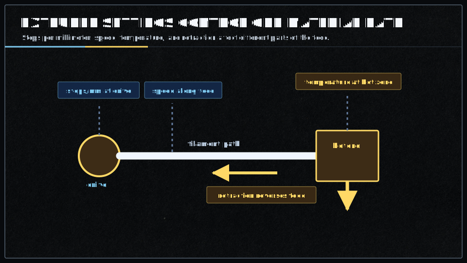
Number of stepper motor steps required to move one millimeter of filament through the extruder — a critical calibration value. Depends on your stepper motor steps/revolution (typically 200 for 1.8° motors), microstepping setting (e.g. 16x = 3200 steps/rev), and your extruder gear ratio/hobbed bolt diameter. Calculate as: Fine-tune by extruding a known length and measuring actual extrusion. Can be adjusted at runtime with |
||
|
Filament diameter in millimeters for volumetric extrusion mode. When set to a value greater than
Can be changed at runtime with |
||
|
Maximum acceleration for the extruder stepper motor in Higher values allow faster speed changes but may cause filament grinding or skipped steps if too aggressive; lower values produce smoother extrusion but may cause artifacts during rapid direction changes. Typical values: Affects extruder-only moves (retractions) and the E-axis component of combined moves. Adjust based on your extruder's mechanical capabilities and filament characteristics. Can be changed at runtime with |
||
|
Maximum allowable speed for the extruder stepper motor in Typical values: Too high a value may cause grinding or skipped steps; too low limits print speed. Affects both printing moves and retractions, and can be set per-extruder for multi-extruder setups. |
||
|
Pin for the extruder stepper motor driver's step signal. Each step pulse moves the motor one microstep according to the driver's microstepping configuration, toggling high/low to create the pulse train that drives the motor.
Step frequency equals |
||
|
Pin for the extruder stepper motor driver's direction signal. Controls whether the motor rotates forward (extrude) or backward (retract); the direction pin must be set before step pulses are sent. Typical Smoothieboard pins: Test direction by sending |
||
|
Pin for the extruder stepper motor driver's enable signal. When active, the motor driver is powered and holds position with full torque; when inactive, the driver is disabled and the motor freewheels (no holding torque). Typical Smoothieboard pins: The motor automatically enables before moves and can disable after a timeout (see |
||
|
X-axis offset of this extruder's nozzle from the primary extruder (T0), in millimeters. Used only in multi-extruder setups to compensate for physical nozzle position differences; the firmware automatically applies these offsets when switching tools with Positive values mean this extruder's nozzle is to the right of T0. Measure the offset by homing, moving to a reference point with T0, switching to this tool, and measuring the distance needed to return to the same point. The primary extruder (T0) should always have offsets of |
||
|
Y-axis offset of this extruder's nozzle from the primary extruder (T0), in millimeters. Used only in multi-extruder setups to compensate for physical nozzle position differences. Positive values mean this extruder's nozzle is toward the back (away from Y=0) compared to T0. See Must be accurately calibrated for proper layer alignment when switching between extruders during multi-material or multi-color prints. |
||
|
Z-axis offset of this extruder's nozzle from the primary extruder (T0), in millimeters. Used only in multi-extruder setups to compensate for different nozzle heights — critical for proper first layer when switching extruders. Positive values mean this extruder's nozzle is higher (further from the bed) than T0. Calibrate by homing Z, moving to a known position with T0, switching to this tool, and measuring the height difference. Even small differences (0.05mm) can cause first layer problems. Some slicers can compensate for Z-offset in G-code, but it's best to configure it in firmware for consistent behavior across all print jobs. |
||
|
Amount of filament to retract during firmware retraction, in millimeters. Used by
Too little retraction causes stringing; too much can cause clogs or air gaps. The total retract amount includes this length plus |
||
|
Speed at which filament is retracted during firmware retraction, in
Faster retractions reduce stringing but may cause grinding or skipped steps if too fast. Direct drive can typically handle faster retractions than Bowden. Speed should be fast enough to quickly relieve pressure but not so fast that it damages filament or causes extruder jamming. Can be changed at runtime with |
||
|
Additional length of filament to extrude when recovering (unretract) beyond the retracted amount. Used by
Compensates for material properties, oozing during travel, or pressure changes in the melt zone. Fine-tune to eliminate blobs (reduce value) or gaps (increase value) after travel moves. Can be changed at runtime with |
||
|
Speed at which filament is recovered (unretracted) during firmware unretraction, in
Slower recovery speeds help prevent blobs and allow time for pressure in the nozzle to build back up smoothly. Too fast can cause blobs; too slow can cause gaps at the start of extrusion. Should generally be less than |
||
|
Amount to lift the Z-axis during retraction, in millimeters (Z-hop / Z-lift feature). When
Z-hop reduces the chance of the nozzle dragging through or knocking over printed parts during travel moves — especially useful for tall thin features, parts with significant Z-variation, or materials prone to warping. Trade-off: increases print time due to extra Z movements. Can be changed at runtime with |
||
|
Speed for Z-axis movement during Z-lift operations, in
Faster Z-lift reduces travel time overhead but may cause ringing or mechanical stress on Z-axis components. Should not exceed the Z-axis maximum speed. Can be changed at runtime with |