This adapter is designed for Smoothieboard V1 and is NOT compatible with Smoothieware V2.
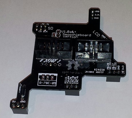
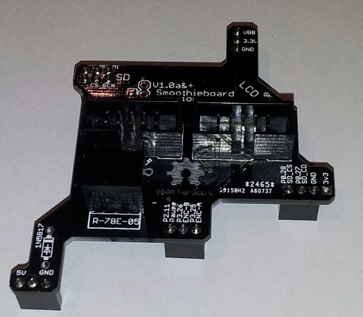
RRD GLCD Adapter board
This adapter allows you to connect a Reprapdiscount GLCD panel to a Smoothieboard easily.
Display Options Comparison
Smoothieware V1 (Smoothieboard):
- Smoothiepanel (recommended)
- RRD GLCD with this adapter
- Various LCD character displays
Smoothieware V2:
- ST7920-based displays (built-in support)
- TM1638-based displays (built-in support)
- Note: This RRD GLCD adapter is NOT compatible with V2 hardware
All of the panel’s functionalities are available:
- Display
- Encoder selector
- Button
- Buzzer
- SD card
Open Hardware
The Source is on GitHub
Getting one
The RRDGLCD Adapter can be found from various electronics suppliers or built from the GitHub source.
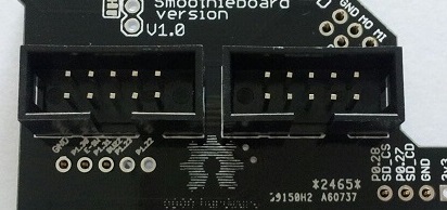
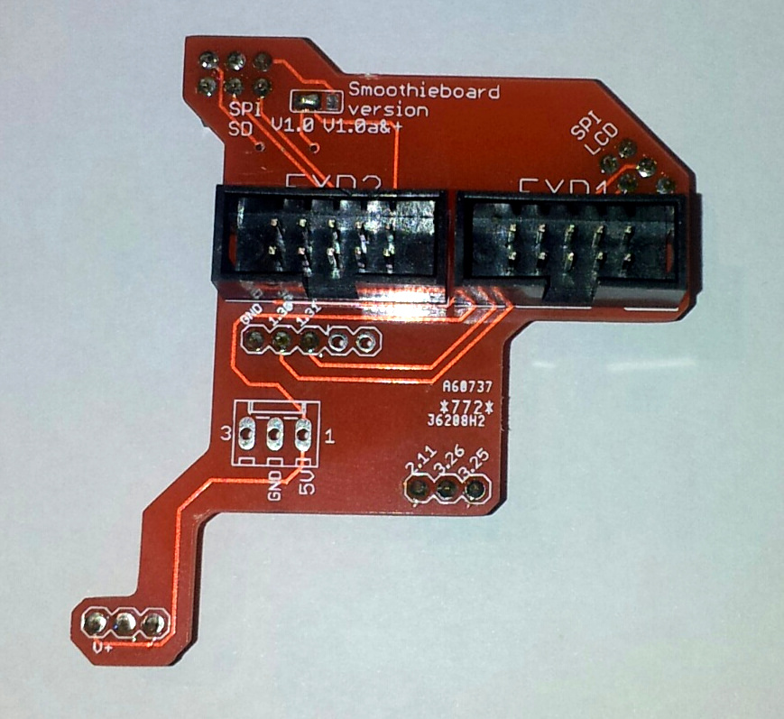
Assembly
Place the 3-pin connectors below the PCB
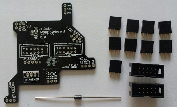
And solder
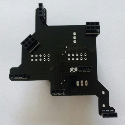
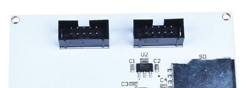
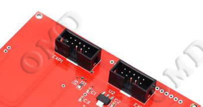
Mount the EXP1 & EXP2 connectors, and solder
On some RRDGLCD the connector are reversed
Power supply
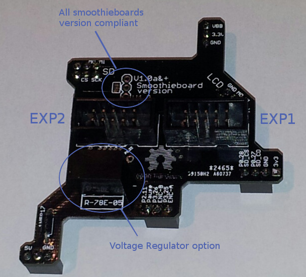
If Smoothieboard has a good 5V regulator, or a 5V power supply, the panel of the power supply can be drawn from this one by means of a diode (ex 1N5817).
If not, please install a voltage regulator Recom 785.0-1
The diode and regulator may be mounted at the same time.
Configuration
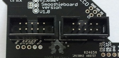
The adapter is configured for Smoothieboard v1.0a and newer.
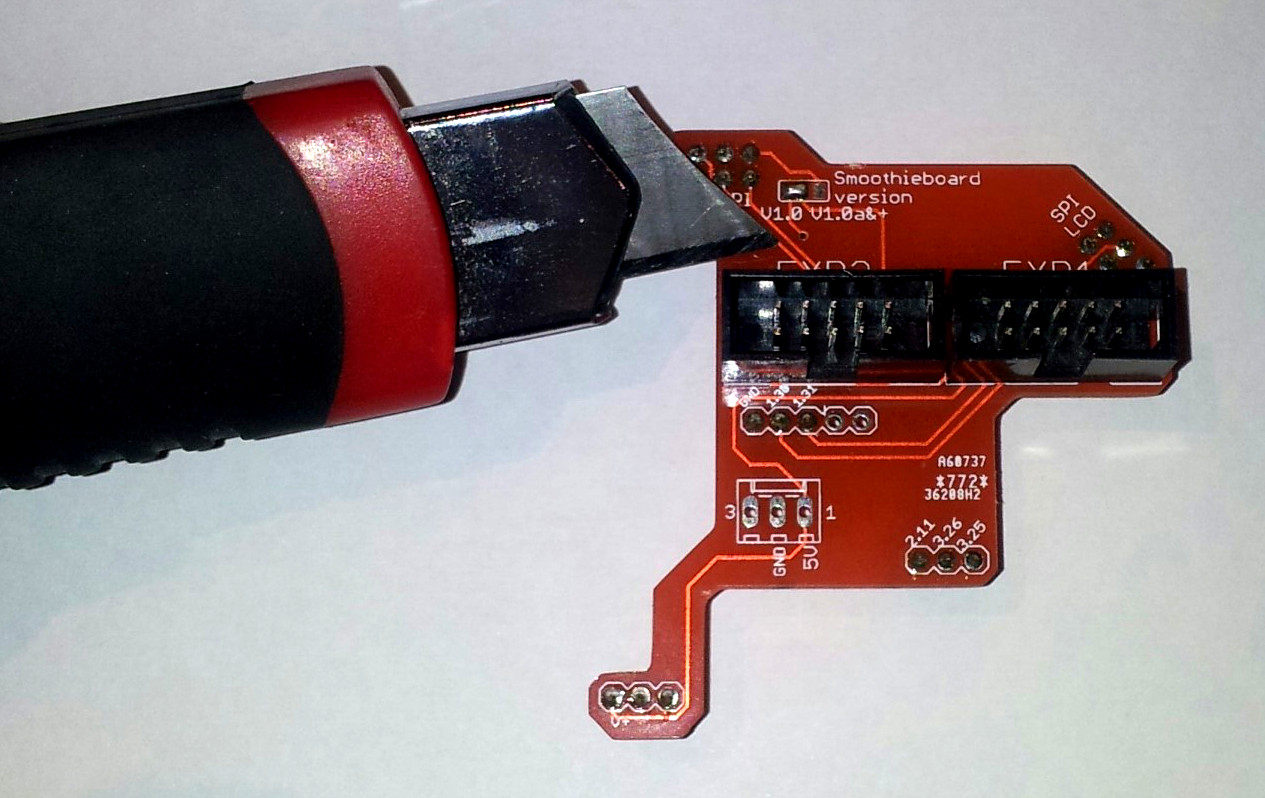
For v1.0 Smoothieboard, configure the PCB
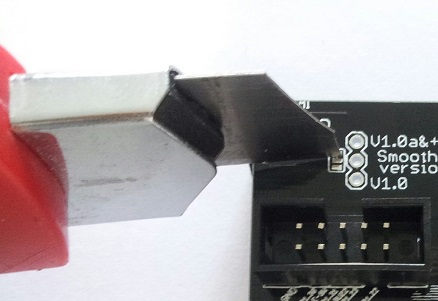
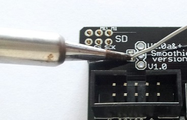
Cut the jumper track, and drop a welding goute on the other part of the jumper.
Use
Solder the connector missing
Update firmware (version after October 2014), see Flashing Smoothie firmware
Edit the config file on the µSD:
V1 Configuration (flat namespace):
# config settings
panel.enable true # set to true to enable the panel code
panel.lcd reprap_discount_glcd # set type of panel
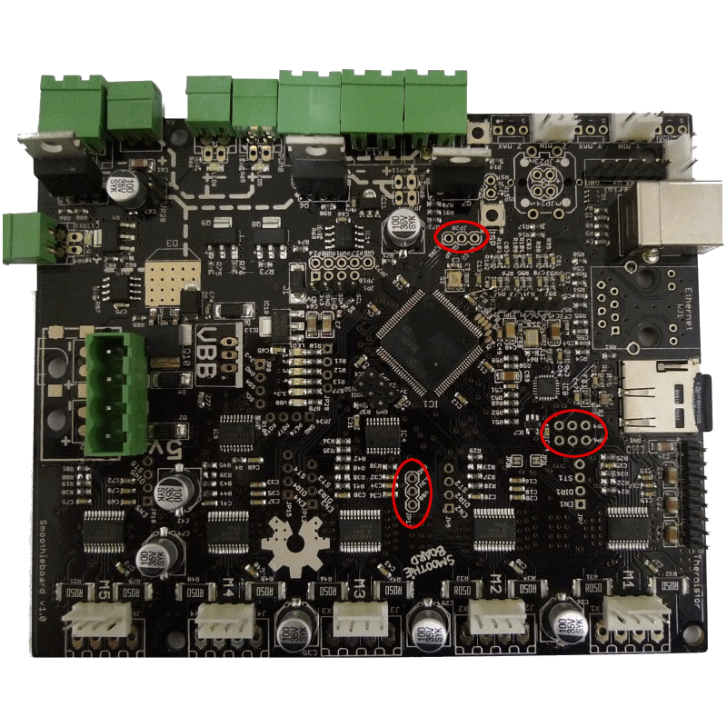
panel.spi_channel 0 # spi channel to use ; GLCD EXP1 Pins 3,5 (MOSI, SCLK)
panel.spi_cs_pin 0.16 # spi chip select ; GLCD EXP1 Pin 4
panel.encoder_a_pin 3.25!^ # encoder pin ; GLCD EXP2 Pin 3
panel.encoder_b_pin 3.26!^ # encoder pin ; GLCD EXP2 Pin 5
panel.click_button_pin 1.30!^ # click button ; GLCD EXP1 Pin 2
panel.buzz_pin 1.31 # pin for buzzer ; GLCD EXP1 Pin 1
panel.back_button_pin 2.11!^ # 2.11 menu back ; GLCD EXP2 Pin 8
# setup for external sd card on the GLCD which uses the onboard sdcard SPI port
panel.external_sd true # set to true if there is an extrernal sdcard on the panel
panel.external_sd.spi_channel 1 # set spi channel the sdcard is on
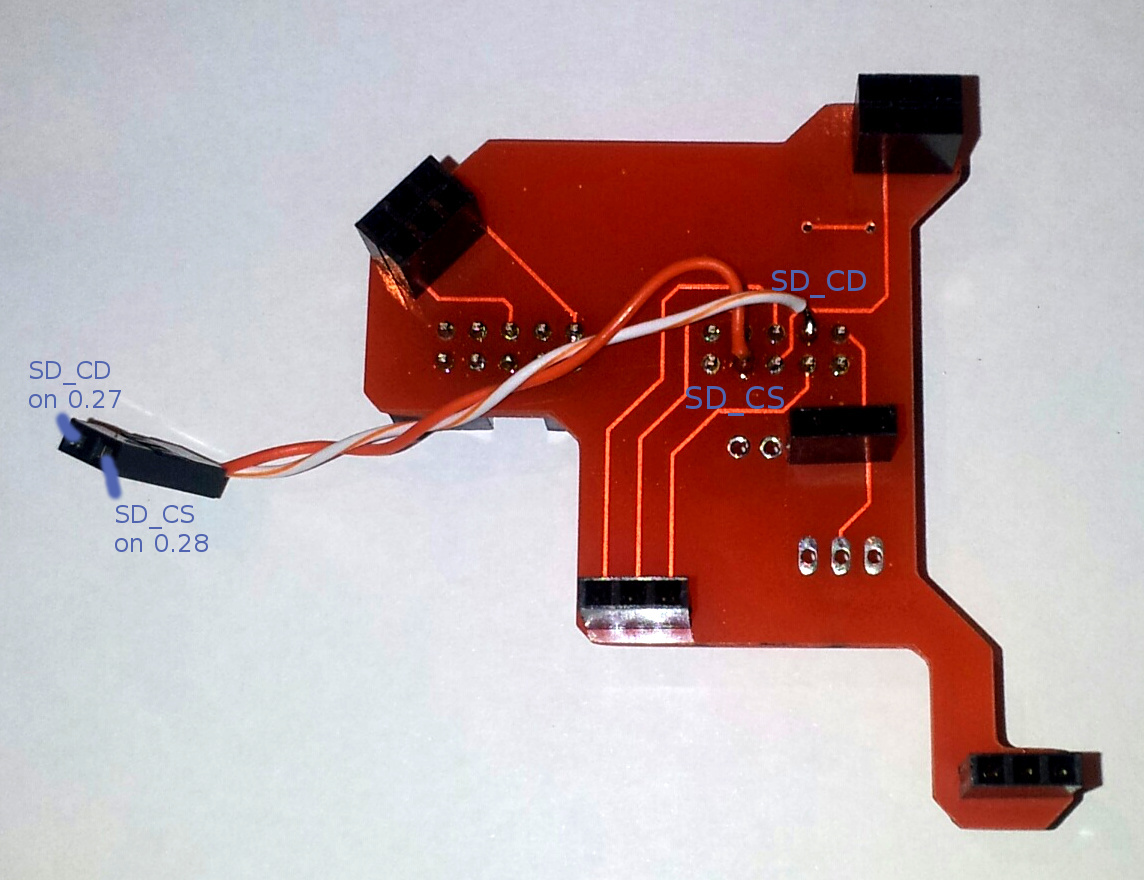
panel.external_sd.spi_cs_pin 0.28 # set spi chip select for the sdcard (or any spare pin)
panel.external_sd.sdcd_pin 0.27!^ # sd detect signal (set to nc if no sdcard detect) (or any spare pin)
V2 Configuration (INI sections):
[panel]
enable = true                      # set to true to enable the panel code
lcd = reprap_discount_glcd         # set type of panel
spi_channel = 0                    # spi channel to use  ; GLCD EXP1 Pins 3,5 (MOSI, SCLK)
spi_cs_pin = P0_16                 # spi chip select     ; GLCD EXP1 Pin 4
encoder_a_pin = P3_25!^            # encoder pin         ; GLCD EXP2 Pin 3
encoder_b_pin = P3_26!^            # encoder pin         ; GLCD EXP2 Pin 5
click_button_pin = P1_30!^         # click button        ; GLCD EXP1 Pin 2
buzz_pin = P1_31                   # pin for buzzer      ; GLCD EXP1 Pin 1
back_button_pin = P2_11!^          # 2.11 menu back      ; GLCD EXP2 Pin 8

[panel.external_sd]
enable = true                      # set to true if there is an external sdcard on the panel
spi_channel = 1                    # set spi channel the sdcard is on
spi_cs_pin = P0_28                 # set spi chip select for the sdcard (or any spare pin)
sdcd_pin = P0_27!^                 # sd detect signal (set to nc if no sdcard detect) (or any spare pin)
If you do not want to use the buzzer, leaving out the panel.buzz_pin line will leave the pin floating.
As there is no pull-down on the buzzer, it will keep buzzing.
To avoid this, you can either solder a pull-down resistor on the adapter board or you can use this little hack:
V1 Configuration:
switch.nonoise.enable                        true
switch.nonoise.output_pin                    1.31v
switch.nonoise.output_type                   digital
V2 Configuration:
[switch]
nonoise.enable = true
nonoise.output_pin = P1_31v
nonoise.output_type = digital
This will create a pseudo-switch that does nothing, but it will enable the pull-down on the pin.
You have to leave out the panel.buzz_pin line.
The V1 of this adapter was not capable of accessing the panel’s SD card slot.
This functionality can be made available on the v1 by cutting track on PCB
And soldering a cable under the PCB