Pin Configuration
A “pin” is an input or output on the Smoothieboard.
In a lot of cases (step/direction for external stepper motors, button inputs), you can use any pin for any use.
In other cases, a given pin is tied to a given peripheral on the board.
See Pinout to learn about which pins are where.
You can have a pin’s output inverted by adding a ! after this pin’s number in the config line, example:
my_pin_name 1.19!
my_pin_name PB3!
There are other modifiers for pins:
| Modifier | Symbol | Description |
|---|---|---|
| Invert pin | ! |
Exclamation mark |
| Open drain | o |
Lowercase O letter |
| Pull up | ^ |
Caret, Shift+6 on QWERTY keyboards (Default on most pins) |
| Pull down | v |
Lowercase v letter |
| No pullup | - |
Minus sign |
| Repeater mode | @ |
At / Arobase sign |
| No modifier | If you do not set any option/modifier for your pin, it will be in pullup mode as if it had ^ specified |
The main example of this is the endstop inputs, which have on-board pull-up resistors, meaning trying to deactivate pull-ups in configuration (
- for them) will not work (configuration cannot deactivate/remove physically present pull-up resistors, it can only act on pull-up pin-configuration peripherals "inside" the chip).
Understanding Pin Modes
The following sections explain what each pin mode means and when you would use it in your 3D printer or CNC mill setup.
Open-Drain Mode (o)
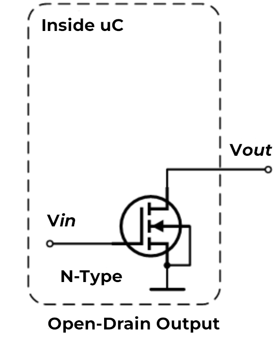
What it is: An open-drain pin is like a switch that can only connect to ground (0V) or disconnect completely. Think of it like a light switch that can only turn the light off or leave it “floating” - it cannot actively turn the light on by itself.
How it works: When the pin is active, it connects to ground (pulls the voltage down to 0V). When inactive, it simply disconnects and lets other components control the voltage on that wire.
Why it matters for 3D printers/CNC: Open-drain is useful when multiple devices need to share the same signal wire. For example:
- Multiple endstops on one pin: If you wire several endstop switches in series, they can all share one input pin using open-drain. When any switch triggers, it pulls the signal to ground.
- Shared alarm signals: When multiple devices need to signal an error condition on the same wire.
- Level shifting: When connecting 5V devices to 3.3V pins, open-drain lets you safely interface between different voltage levels.
When to use it:
Use open-drain (o) when you need to connect multiple switches or sensors to a single pin, or when interfacing with devices that expect open-collector/open-drain outputs.
Pull-Up Mode (^)
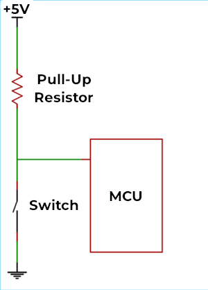
What it is: A pull-up resistor is like a weak spring that gently pulls the pin voltage up to 3.3V when nothing else is controlling it. It’s the default mode for most pins on the Smoothieboard.
How it works: Inside the microcontroller chip, there’s a resistor (typically around 50kΩ) connected between the pin and the 3.3V power supply. This resistor is “weak” - any external signal can easily override it. When you connect a switch or sensor that pulls the pin to ground, it wins over the pull-up resistor.
Why it matters for 3D printers/CNC: Pull-up mode is the standard way to connect switches and sensors:
- Endstop switches: When the switch is open (not triggered), the pull-up keeps the pin at 3.3V (high). When the switch closes, it connects the pin to ground, reading as 0V (low).
- Thermistor connections: Many temperature sensors work with pull-up resistors to create a voltage divider.
- Simple wiring: You only need two wires to your switch - one to the pin and one to ground. No separate power wire needed.
When to use it:
Use pull-up (^) for most switches, buttons, and sensors. This is the default and works for the majority of inputs on a 3D printer or CNC mill. If you don’t specify a modifier, the pin automatically uses pull-up mode.
Pull-Down Mode (v)
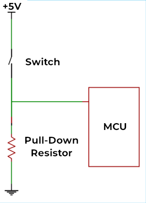
What it is: A pull-down resistor is the opposite of pull-up - it’s like a weak spring that gently pulls the pin voltage down to 0V (ground) when nothing else is controlling it.
How it works: Instead of connecting to 3.3V, the internal resistor connects between the pin and ground. The pin reads as 0V (low) by default, and only reads high (3.3V) when something actively drives it high.
Why it matters for 3D printers/CNC: Pull-down is less common but useful in specific situations:
- Active-high sensors: Some sensors output 3.3V when triggered and disconnect when not triggered. Pull-down ensures the pin reads 0V when disconnected.
- Normally-closed switches: If you’re using a switch that’s closed by default and opens when triggered, pull-down can simplify your wiring.
- Positive logic preference: When you want the pin to read “low” in the idle state and “high” when activated.
When to use it:
Use pull-down (v) when connecting sensors or switches that provide a positive voltage when active, or when you specifically want the opposite behavior of pull-up mode. This is relatively rare in typical 3D printer setups.
Repeater Mode (@)
What it is: Repeater mode is a hybrid that tries to “remember” the last signal it saw and weakly hold it there. It acts like both a pull-up and pull-down at the same time, maintaining whatever state the pin was last in.
How it works: The pin has circuitry that detects whether the last signal was high or low, then uses a weak resistor to keep it in that state. If the pin was pulled high, it acts like a pull-up. If it was pulled low, it acts like a pull-down. It “repeats” the last state it saw.
Why it matters for 3D printers/CNC: Repeater mode is useful in specific edge cases:
- Long wire runs: When you have very long cables (several meters) that might pick up electrical noise, repeater mode helps maintain signal stability.
- Floating inputs: When a pin might be disconnected temporarily but needs to maintain its last known state.
- Reducing noise: The weak holding force helps filter out brief noise spikes on the wire.
When to use it:
Use repeater mode (@) when you have long cables prone to noise, or when you need a pin to maintain its state even when the signal source briefly disconnects. This is the least commonly used mode in typical 3D printer or CNC setups - most users will never need it.
^) or pull-down (v) modes. Do not enable repeater mode simply because you think it will "make things better" - it is designed for very specific edge cases and is rarely needed in typical configurations.
Combining Multiple Modifiers
Important: You can use multiple modifiers on the same pin by placing them one after another. The pin configuration system allows you to combine different flags to achieve exactly the behavior you need.
Syntax:
my_pin_name 2.11!o^
In this example, pin
my_pin_name PC7!o^
In this example, pin PC7 is configured with:
!- Inverted outputo- Open-drain mode^- Pull-up enabled
Common Useful Combinations
Here are some practical combinations you might use in your 3D printer or CNC setup:
1. Inverted with Pull-up (!^)
endstop_pin 1.24!^
endstop_pin PA5!^
This is extremely common for endstops. The pull-up keeps the pin high (3.3V) when the switch is open, and the inversion means the firmware reads this as “not triggered.” When the switch closes, the pin goes to ground, and the inversion makes the firmware read it as “triggered.”
Why it’s useful: Many endstop configurations expect the opposite logic from what the hardware naturally provides. This lets you match your firmware expectations without rewiring.
2. Open-drain with Pull-up (o^)
shared_alarm_pin 2.11o^
shared_alarm_pin PC7o^
This creates a “wired-OR” configuration where multiple devices can signal on the same wire. Each device uses open-drain to pull the line low when active, and the pull-up resistor keeps it high when no device is signaling.
Why it’s useful: You can connect multiple safety sensors (like door switches, emergency stops, or temperature alarms) to a single pin. Any sensor triggering will pull the pin low.
3. Inverted Open-drain (!o)
output_pin 1.18!o
output_pin PB8!o
This inverts an open-drain output, which can be useful when controlling devices that expect active-high signals while using open-drain for level shifting.
Why it’s useful: When interfacing with 5V logic devices from your 3.3V Smoothieboard, you can use open-drain with a pull-up resistor to 5V on the other device. The inversion lets you maintain the expected logic levels.
4. No Pull with Invert (!-)
external_driver_pin 2.5!-
external_driver_pin PD12!-
Disables internal pull resistors and inverts the signal. This is useful when external hardware provides its own pull resistors and you need inverted logic.
Why it’s useful: Some external stepper drivers or relay boards have their own pull-up or pull-down resistors. Using - prevents conflicts between internal and external resistors, and ! adapts the logic level.
5. Pull-down with Invert (!v)
sensor_pin 1.29!v
sensor_pin PE6!v
Uses pull-down to keep the pin low by default, then inverts the reading. This means the firmware sees “high” when nothing is connected and “low” when the sensor activates and pulls the pin high.
Why it’s useful: Some active sensors output a positive voltage when triggered. Pull-down keeps noise low when disconnected, and the inversion can match your firmware’s expected logic.
Important Notes on Combining Modifiers
- Order doesn’t matter -
!o^and^o!ando!^all do the same thing - Conflicting modifiers - Don’t combine pull-up (
^) and pull-down (v) on the same pin, or pull-up (^) with no-pull (-). Only use one pull mode at a time. - Logical combinations - Think through what each modifier does and make sure they work together logically
- Test your setup - When using multiple modifiers, always test that the pin behaves as expected before relying on it for critical functions like endstops or safety sensors
Quick Reference: Common Combinations
| Combination | Config | Use Case |
|---|---|---|
| Inverted pull-up | !^ |
Endstops with reversed logic |
| Open-drain + pull-up | o^ |
Multiple sensors on one pin |
| Inverted open-drain | !o |
Level shifting with inverted logic |
| Inverted no-pull | !- |
External pull resistors with reversed logic |
| Inverted pull-down | !v |
Active-high sensors with reversed logic |
Default Pin Assignments
This table shows the default pin assignments for common functions:
| Function | Pin | Notes |
|---|---|---|
| X Step | Alpha stepper | |
| X Dir | Alpha stepper | |
| Y Step | Beta stepper | |
| Y Dir | Beta stepper | |
| Z Step | Gamma stepper | |
| Z Dir | Gamma stepper | |
| E0 Step | Delta stepper / Extruder | |
| E0 Dir | Delta stepper / Extruder | |
| Min X | X endstop | |
| Min Y | Y endstop | |
| Min Z | Z endstop | |
| Max X | X max endstop | |
| Max Y | Y max endstop | |
| Max Z | Z max endstop | |
| Hotend | PWM output | |
| Bed | PWM output |
Configuration Example
Here’s a typical configuration showing stepper and endstop pin assignments:
# Stepper and endstop configuration
alpha_step_pin                       2.0
alpha_dir_pin                        0.5!
alpha_en_pin                         0.4
alpha_min_endstop                    1.24^
alpha_max_endstop                    1.25^

beta_step_pin                        2.1
beta_dir_pin                         0.11!
beta_en_pin                          0.10
beta_min_endstop                     1.26^
beta_max_endstop                     1.27^
# Stepper and endstop configuration
alpha_step_pin                       PF0
alpha_dir_pin                        PF1!
alpha_en_pin                         PC0
alpha_min_endstop                    PG0^
alpha_max_endstop                    PG3^

beta_step_pin                        PF2
beta_dir_pin                         PF3!
beta_en_pin                          PC3
beta_min_endstop                     PG1^
beta_max_endstop                     PG4^
Summary:
- Pull-up (
^) - Default, best for switches and sensors (pin high by default, goes low when triggered) - Pull-down (
v) - Opposite of pull-up (pin low by default, goes high when triggered) - Open-drain (
o) - For sharing pins between multiple devices or level shifting - Repeater (
@) - For long cables or maintaining state (rarely needed)