Endstops
It’s essentially just a switch
End-stops are small interrupters that you put at the end of each of your axes.
When you boot your machine up, Smoothie has no way of knowing the position of each axis.
When it starts a print, Smoothie moves the axis until it touches that interrupter, and when it is hit, it declares that that is position 0 for that axis. And does so for all axes.
This allows Smoothie to then precisely know where everything is relative to that initial position.
It is quite convenient as it saves you the hassle of actually moving the machine into that position when you want to start a print. Automation is great.
However, end-stops are not necessary, you could do without them. They are just so convenient that most machines use them.
End-stops can also be used as limit switches which prevent the machine from attempting to move beyond the physical limits of the axis (by pausing/stopping movement when triggered), see the Endstops page for details about configuring Smoothie to use End Stops as limit switches.
• Homing (move til endstop is hit)
• Hard endstops (stop when endstop is hit, which is optional)
• Soft endstop (once homed, do not go further than a set position, which is also optional)
This does not mean ANY kind of feature is missing, you can still do everything you expect, this is just a subtility in vocabulary and in how configuration is organized, that new users are generally fine with, except if they come from another system which has a different paradigm.
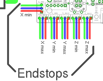
There are 6 of them, two for each axis
Mechanical endstop wiring
This will concentrate on the most common type of end-stops: the mechanical ones.
Other types exist like optical or hall-o sensors.
There are plenty of fun and futuristic endstop types around: optical, laser, magnetic, force-sensitive, infrared, inductive, etc...
However, please note that the general feedback from the community, is that most of those are either less precise, less repeatable, or much more difficult to get to "work right", compared to the classical "mechanical" endstop.
The mechanical endstop is actually likely the most precise, repeatable and easy to get to work option you have at your disposal. Just because these other options exist and have been explored by the community, does not mean they are better.
You might happen have a good reason to use a fancy endstop, but if you don't, it's likely a good idea to stick with a mechanical one.
Mechanical end-stops are simple interrupters: when not pressed, they do not let the current pass, when pressed, they let the current pass. By connecting a digital input pin on the Smoothieboard to the interrupter, and connecting the other side of the interrupter to Ground, the Smoothieboard can read whether or not it is connected to Ground, and therefore whether or not the end-stop is pressed.
Most mechanical end-stops have 3 connection points, to which you have to attach your wires:
- C: Common
- NO: Normally Open, meaning it is not connected to C when the interrupter is not pressed, and connected to C when the interrupter is pressed.
- NC: Normally Closed, meaning it is connected to C when the interrupter is not pressed, and not connected to C when the interrupter is pressed. {::nomarkdown}

You want to connect the Signal (green in the schematic) and Ground (blue in the schematic) pins for the end-stop on the Smoothieboard, to the C and NC connection points on the end-stop.
{:/nomarkdown}
For each endstop, we connect C to Signal and NC to Ground because this means the digital input pin (endstop connector) will be connected to Ground in its normal state and cut from Ground when the button is pressed. This approach is less prone to noise than the reverse. See here for more information.
Another positive effect of this approach is, that if a wire breaks for some reason you get the same signal as if the endstop is pressed. That makes sure that even with a damaged wire you are not able to overrun the endstop.
Make absolutely sure that you do not connect VCC (red) and GND (blue) to a mechanical (microswitch) endstop! Depending on your wiring this may fry your smoothieboard instantly or when the switch gets pressed. There is certain wiring where this won't happen when you switch the signal between VCC and GND, but if you're not careful enough you will damage your board.
You want to connect your X end-stop to the X min pins, Y end-stop to the Y min pins, and Z end-stop to the Z min pins.
Powered endstops wiring
Mechanical endstops are simple switches, they simply let a signal pass through, or not, allowing us to detect their status with an endstop input. It has no intelligence of its own.
There are more sophisticated endstops. Those are “powered endstops”, for example: Hall-O (magnetic) or optical endstops.
The only difference between a mechanical endstop and those powered endstops is that they require being provided with 5V power.
This means that where for a mechanical endstop you connect the Signal and GND pins, for a powered endstop, you connect the Signal, GND and 5V pins.
Other than this, it works exactly the same as a mechanical endstop: The Signal pin receives something different depending on whether the endstop is triggered or not.
Different powered endstops have different behaviors:
Some connect Signal to Ground when triggered, and Signal to 5V when not triggered.
Others connect Signal to 5V when triggered, and Signal to Ground when not triggered.
To know exactly what your endstop does, see its documentation.
If once wired, your endstop reports the opposite of what it should via the 1 when triggered/pushed, and 0 when not triggered), see the “Testing” section.
Some endstops might require removing their “pull-up” configuration, in this case, change:
alpha_min_endstop 1.28^
To:
alpha_min_endstop 1.28
And if you need it to be a pull-down, change it to:
alpha_min_endstop 1.28v
In some very rare cases, the endstop reading circuit on the Smoothieboard will not be adequate for your endstop type. In this case, you should use a “free” GPIO pin on the Smoothieboard that nothing else uses to connect your endstop to.
See Pinout to find adequate pins.
Testing
The default configuration most probably already has everything you need: the pins are already correct and the default speeds are reasonable.
Once they are wired, you can test your end-stops.
To do this, reset your Smoothieboard, then connect to it using host software like Pronterface or the web interface.
Now connect to your Smoothieboard over the serial interface. Power your machine on by plugging the PSU into the wall.
Now in Pronterface, home one axis by clicking the small “home” icon for that axis. Begin with X, then Y, then Z.
If your axis moves until it hits the end-stop, then stops when it hits it, moves a small distance back, then goes a bit slower back to the end-stop and stops, that end-stop is working fine.
On the other hand, if the axis moves a small distance in the wrong direction, then stops, you have a problem: your Smoothieboard always reads the end-stop as being pressed. So when you ask it to move until the end-stop is hit, it reads it immediately as pressed and stops there.
Another problem can be that the axis moves and never stops, even after the end-stop is physically hit. This means your Smoothieboard actually never reads the end-stop as being pressed.
There is a command that allows you to debug this kind of situation: in Pronterface, enter the “
Smoothie will answer with the status of each endstop like this:
X min:1 Y min:0 Z min:0
This means: X endstop is pressed, Y and Z endstops are not pressed.
Use a combination of this command, and manually pressing end-stop, to determine what is going on.
If an end-stop is read as always pressed, or never pressed, even when you press or release it, then you probably have a wiring problem, check everything.
If an endstop is read as pressed when it is not, and not pressed when it is, then your end-stop is inverted.
You can fix that situation by inverting the digital input pin in your configuration file. For example if your X min endstop pin is inverted, change:
alpha_min_endstop 1.28^
To:
alpha_min_endstop 1.28^!
Here is the exact mapping of pin names to inputs on the board:
| Endstop | X MIN | X MAX | Y MIN | Y MAX | Z MIN | Z MAX |
|---|---|---|---|---|---|---|
| Config value | alpha_min | alpha_max | beta_min | beta_max | gamma_min | gamma_max |
| Pin name |
| Endstop | X MIN | X MAX | Y MIN | Y MAX | Z MIN | Z MAX |
|---|---|---|---|---|---|---|
| Config value | minx | maxx | miny | maxy | minz | maxz |
| Pin name |
For complete pinout information, see the Smoothieboard Pinout documentation.
For complete pinout information, see your board’s pinout documentation:
More information can be found here.
Configuration
Quick Migration Guide
Here’s a quick reference for migrating endstop configuration from V1 to V2 format:
V1 Configuration (flat format):
alpha_min_endstop                            1.24^!
alpha_homing_direction                       home_to_min
alpha_min                                    0
alpha_max                                    200

beta_min_endstop                             1.26^!
beta_homing_direction                        home_to_min
beta_min                                     0
beta_max                                     200

gamma_min_endstop                            1.28^!
gamma_homing_direction                       home_to_min
gamma_min                                    0
gamma_max                                    200

alpha_max_travel                             500
beta_max_travel                              500
gamma_max_travel                             500
V2 Configuration (INI format):
[alpha endstop]
min.pin = 1.24^!
homing_direction = home_to_min
min_position = 0
max_position = 200
max_travel = 500

[beta endstop]
min.pin = 1.26^!
homing_direction = home_to_min
min_position = 0
max_position = 200
max_travel = 500

[gamma endstop]
min.pin = 1.28^!
homing_direction = home_to_min
min_position = 0
max_position = 200
max_travel = 500
Configuration Options
The config settings for Endstops are as follows:
| V1 Setting | V2 Setting | Description |
|---|---|---|
| Always enabled if configured in v2 | Master enable switch for the traditional root-level endstop configuration method. When set to |
|
| Enables CoreXY-specific homing behavior. When enabled, X and Y axes home individually (one at a time) rather than simultaneously. Both X and Y motors are stopped when either endstop is triggered during homing. CRITICAL: Must be enabled for CoreXY and H-Bot kinematics to prevent incorrect homing behavior. | ||
| Enables linear delta robot homing behavior. When enabled, |
||
| Enables rotary delta robot homing behavior. Similar to linear delta, but endstop positions represent actuator angles (in degrees), not cartesian coordinates. CRITICAL: Must be enabled for rotary delta kinematics. | ||
| Enables SCARA robot arm homing behavior. When enabled, disables arm solution during homing (homes in actuator space, not cartesian space). Resets arms to plausible minimum angles (-30, 30, 0) before homing to prevent extreme positions. CRITICAL: Must be enabled for SCARA kinematics. | ||
| Specifies a custom homing order, forcing axes to home one at a time in the specified sequence. Must be 3-6 characters specifying axis letters (XYZABC) in desired order. IMPORTANT: Any axis not specified in the string will NOT be homed. Examples: |
||
| Controls whether the Z axis homes before or after the X and Y axes. When |
||
| Controls whether the machine automatically moves to the origin (0,0 or 0,0,0) after homing completes. Cartesian default: |
||
| Not documented in v2 | If enabled, moves to a predefined park position after homing instead of moving to origin. The park position is set using |
|
| Number of consecutive reads required to confirm a limit switch trigger. This provides debouncing for limit switches (not homing endstops). IMPORTANT: Only used for limit switches (when |
||
| Debounce time in milliseconds for homing endstops. When an endstop is triggered during homing, it must remain triggered for this duration before being accepted as a valid trigger. IMPORTANT: Only used for homing endstops during |
||
| DELTA/SCARA ONLY. Software trim for alpha tower/joint endstop. Compensates for small variations in endstop positions between towers. Positive values move the effective endstop position toward the endstop (shortens tower). Negative values move away from endstop (lengthens tower). Units are millimeters for linear deltas, degrees for rotary deltas. Set via |
||
| DELTA/SCARA ONLY. Software trim for beta tower/joint endstop. Compensates for small variations in endstop positions between towers. Positive values move the effective endstop position toward the endstop (shortens tower). Negative values move away from endstop (lengthens tower). Units are millimeters for linear deltas, degrees for rotary deltas. Set via |
||
| DELTA/SCARA ONLY. Software trim for gamma tower/joint endstop. Compensates for small variations in endstop positions between towers. Positive values move the effective endstop position toward the endstop (shortens tower). Negative values move away from endstop (lengthens tower). Units are millimeters for linear deltas, degrees for rotary deltas. Set via |
||
| Alpha (X axis or alpha tower) minimum limit endstop pin. Set to |
||
| Alpha (X axis or alpha tower) maximum limit endstop pin. Set to |
||
| In which direction to home. If set to |
||
| This gets loaded after homing when |
||
| This gets loaded after homing when |
||
| This determines how far the X axis can travel looking for the endstop before it gives up. CRITICAL: Set this value larger than your actual machine travel distance to prevent false failures. | ||
| If set to true, the machine will stop if one of the alpha (X axis or alpha tower) endstops are hit during normal operation. Machine halts and enters ALARM state. | ||
| Speed, in millimetres/second, at which to home for the alpha actuator (X axis or alpha tower). This is the first phase of the two-stage homing process. | ||
| Speed, in millimetres/second, at which to re-home for the alpha actuator (X axis or alpha tower) once the endstop is hit once. This is the precision phase of the two-stage homing process. Slower speeds provide more accurate and repeatable homing positions. | ||
| Distance to retract the alpha actuator (X axis or alpha tower) once the endstop is first hit, before re-homing at a slower speed. Must be large enough to fully release the endstop switch. | ||
| Beta (Y axis or beta tower) minimum limit endstop pin. Set to |
||
| Beta (Y axis or beta tower) maximum limit endstop pin. Set to |
||
| In which direction to home. If set to |
||
| This gets loaded after homing when |
||
| This gets loaded after homing when |
||
| This determines how far the Y axis can travel looking for the endstop before it gives up. CRITICAL: Set this value larger than your actual machine travel distance to prevent false failures. | ||
| If set to true, the machine will stop if one of the beta (Y axis or beta tower) endstops are hit during normal operation. Machine halts and enters ALARM state. | ||
| Speed, in millimetres/second, at which to home for the beta actuator (Y axis or beta tower). This is the first phase of the two-stage homing process. | ||
| Speed, in millimetres/second, at which to re-home for the beta actuator (Y axis or beta tower) once the endstop is hit once. This is the precision phase of the two-stage homing process. Slower speeds provide more accurate and repeatable homing positions. | ||
| Distance to retract the beta actuator (Y axis or beta tower) once the endstop is first hit, before re-homing at a slower speed. Must be large enough to fully release the endstop switch. | ||
| Gamma (Z axis or gamma tower) minimum limit endstop pin. Set to |
||
| Gamma (Z axis or gamma tower) maximum limit endstop pin. Set to |
||
| In which direction to home. If set to |
||
| This gets loaded after homing when |
||
| This gets loaded after homing when |
||
| This determines how far the Z axis can travel looking for the endstop before it gives up. CRITICAL: Set this value larger than your actual machine travel distance to prevent false failures. | ||
| If set to true, the machine will stop if one of the gamma (Z axis or gamma tower) endstops are hit during normal operation. Machine halts and enters ALARM state. | ||
| Speed, in millimetres/second, at which to home for the gamma actuator (Z axis or gamma tower). This is the first phase of the two-stage homing process. Z-axis typically uses a slower rate (4-10 mm/s) for safety to prevent bed crashes. | ||
| Speed, in millimetres/second, at which to re-home for the gamma actuator (Z axis or gamma tower) once the endstop is hit once. This is the precision phase of the two-stage homing process. Z-axis often uses the slowest rate (1-5 mm/s) for maximum precision. | ||
| Distance to retract the gamma actuator (Z axis or gamma tower) once the endstop is first hit, before re-homing at a slower speed. Z-axis often uses smaller values (1-3 mm) to minimize travel. Must be large enough to fully release the endstop switch. |
Reading
You can use the
min_x:0 min_y:0 min_z:0 max_x:0 max_y:0 max_z:0
ok
If an endstop is not connected the pin should be set to « nc » (meaning “not connected”), and its value will not be reported.
This is particularly useful when setting up your machine: you can issue the
If an endstop always reports 0, it probably means that it is not wired correctly.
If an endstop’s values are inverted, it probably means you wired the pin as NO when it is NC, or the opposite.
You can reverse a pin in the configuration file by adding or removing a « ! » character after the pin number (see Pin Configuration).
For example, if the beta min endstop is inverted in your diagnostics, change:
beta_min_endstop 1.26^
to:
beta_min_endstop 1.26^!
Homing
You use the
For example:
G28 Z0
will home the Z axis.
And:
G28
will home all axes which have endstops enabled (all three by default).
If your axis is moving away from the endstop when homing, you need to invert your min and max endstops, or invert the direction of the axis, depending on your preference.
Do not set endstops for axes that shall not be homed.
When you home a delta that has non zero trim values, you will find that X and Y are not 0 after homing. This is normal.
If you want X0 Y0 after homing you can set
true in the config, this will move the effector to 0,0 after it homes and sets the trim. However, note this may crash into your endstops, so make sure you enable limit switches, as this will force the carriages off the endstops after homing but before moving to 0,0.
Limit switches
Endstops may be configured to act as limit switches, during normal operations if any enabled limit switch is triggered the system will halt and all operations will stop, it will send a !! command to the host to stop it sending any more data (a recent dev octoprint and recent Pronterface support this).
Sending $X, or sending
To enable endstops as limit switches the following config options can be used, they are disabled by default.
alpha_limit_enable                          true            # set to true to enable X min and max limit switches
beta_limit_enable                           true            # set to true to enable Y min and max limit switches
gamma_limit_enable                          true            # set to true to enable Z min and max limit switches
[endstops.common]
alpha_limit_enable = true            # set to true to enable X min and max limit switches
beta_limit_enable = true             # set to true to enable Y min and max limit switches
gamma_limit_enable = true            # set to true to enable Z min and max limit switches
When one axis is enabled both min and max endstops will be enabled as limit switches, setting an endstop pin to nc will disable it.
The downside is if you home to 0 and at 0 the endstop is triggered going to 0,0 will cause a limit switch to fire. The workaround is to set homing offset to -5 (eg
M206 X-5 Y-5) or enough to back off the endstop so when you go to 0,0 it does not trigger the endstop.That way you can home, and safely go to 0 without triggering a limit switch event. An alternative is to set min/max X/Y to -5 rather than 0.
On some boards you have only 3 endstop connectors, which is not enough to have one connector for each end of each axis, but you can still connect two endstops for each end of each axis by connecting the two endstops on a single connector:
- In series and each connected as normally-closed
- Or in parallel and each connected as normally-open
Soft endstops
Soft(ware) endstops is a feature that allows the board to refuse any command that would put it outside the bounds of the work area.
Note that this feature only functions once the machine has been homed (until then it can’t know where it is). After the machine has been homed this feature is enabled. it can be temporarily disabled using the M211 S0 M-code, and can be enabled again using the M211 S1 M-code.
The configuration is as such:
soft_endstop.enable         true         # Enable soft endstops
soft_endstop.x_min          1            # Minimum X position
soft_endstop.x_max          999          # Maximum X position
soft_endstop.y_min          1            # Minimum Y position
soft_endstop.y_max          499          # Maximum Y position
soft_endstop.z_min          1            # Minimum Z position
soft_endstop.z_max          199          # Maximum Z position
soft_endstop.halt           true         # Whether to issue a HALT state when hitting a soft endstop (if false, will just ignore commands that would exceed the limit)
[soft_endstop]
enable = true         # Enable soft endstops
x_min = 1             # Minimum X position
x_max = 999           # Maximum X position
y_min = 1             # Minimum Y position
y_max = 499           # Maximum Y position
z_min = 1             # Minimum Z position
z_max = 199           # Maximum Z position
halt = true           # Whether to issue a HALT state when hitting a soft endstop (if false, will just ignore commands that would exceed the limit)
Simply add this series of config options to your config file and the machine will start respecting soft endstops.
You can test/debug the feature by issuing the M211 M-code, which will tell you the current status of the soft endstops.
NOTE it is highly recommended that you always enable HALT when a soft endstop is hit, the ignore commands option is VERY dangerous as subsequent commands that are within the soft endstops limit will continue from an arbitrary position causing untold damage.
Usage example with home offsets
Here is a common sequence that you may do to set bed height, this need not be repeated unless the bed changes.
; Home
G28
; move to 5mm above bed
G0 Z5
; then manually jog down until nozzle is on bed or just traps a sheet of thin paper
; sets the Z homing offset based on current position
M306 Z0
G28
G0 Z0
; check nozzle still captures thin sheet of paper
M500
; saves the results in EEPROM equivalent
Changing the origin
The homing position, or origin, is the 0,0 position relative to which the machine moves.
On a delta, the homing position (origin) is automatically the center of the bed.
On a cartesian, however, the homing position (origin) is the point at which the end stops are hit, generally a corner of the machine.
You might want to have a different origin point though.
For example, if your X axis is homing to the max endstop, and that endstop is 200mm away from the machine origin, you can make sure the machine knows where that endstop is relative to your origin point by setting:
alpha_max 200
If your X axis is homing to the min endstop, your work area is 200mm wide, and you want the origin point to be the center of the work area, you can set the origin point to the center of the work area by doing:
alpha_min -100
By default, the machine will home, and set the current position as configured, but will not move to 0,0 after homing. If you want to move to the origin after homing, you need to set move_to_origin_after_home to true.
If you want to learn more about this module, or are curious how it works, Smoothie is Open-Source and you can simply go look at the code, here.
Types of endstops
Sensor Types
When setting up endstops and probes for your CNC machine or 3D printer, choosing the right sensor type is crucial for reliable operation.
Here is a table of the common sensor types, with their pros, cons, and our advice:
| Type | Uses | Pros | Cons | Our rating | Advice |
|---|---|---|---|---|---|
| Mechanical switch | Endstops, retractable Z-probes | Cheap, very durable, very precise/repeatable | None | This is the simplest, and also by chance the best sensor. Don’t use anything else unless you have a very good reason to. Just getting a fancier sensor because it feels cool to do so, is most likely going to bite you in the back quickly. | |
| Optical switch | Endstops, retractable Z-probes | Cheap, durable, very precise/repeatable | Dust can block light path after some time | This can be used in place of mechanical switches in most situations, has similar advantages, and doesn’t produce any sound. | |
| Hall effect | Endstops, bed probe | Fairly cheap, non-contact, variable precision/repeatability | Requires magnets, which accumulates ambient metal dust, can lack repeatability | A fair non-contact option if contact is an issue in your setup. | |
| Inductive | Endstops, bed probe | Non-contact | Expensive, difficult to wire, substandard repeatability, 24-36V requirement, endstop input protection (voltage divider) required | You probably shouldn’t use these unless you have a very good reason. | |
| Capacitive | Endstops, bed probe | Non-contact, can be used with glass bed | Expensive, difficult to wire, substandard repeatability, 24-36V requirement, endstop input protection (voltage divider) required | You probably shouldn’t use these unless you have a very good reason. | |
| Force sensitive resistor (FSR) | Bed probe | Can be used under a glass bed, non-contact, can be very reliable if set up correctly | Difficult to set up correctly, finicky, expensive, analog meaning it requires an adapter, more complex to wire | You probably shouldn’t use these unless you have a very good reason. | |
| IR probes | Z probe, bed probe | Non-contact | Expensive, analog meaning it requires an adapter, terrible repeatability/accuracy, more complex to wire | You probably shouldn’t use these unless you have a very good reason. | |
| Bltouch | Retractable Z-probes | Cheap, very durable, very precise/repeatable, retractable (equivalent to a servo-mounted mechanical switch) | None, other than the added complexity of retracting | The mechanical switches are the best sensors by far, but this is very similar, essentially emulating a servo-mounted mechanical switch. |
Recommendations
For retractable Z-probes, BLTouch sensors provide excellent performance and reliability.
Avoid complex sensors unless you have a specific requirement that justifies the added complexity and cost.
Additional Resources
The Reprap probe page also has information on this that you might find helpful.