Configuration File
One of the really appreciated features of the Smoothie firmware is that it doesn’t require editing source code, compiling, or flashing in order to edit the configuration.
Instead, Smoothie is configured simply by editing a configuration file on its SD card.
This makes Smoothie incredibly user-friendly and accessible, even for beginners.
How to Edit Configuration
Simply edit the configuration file, unmount/safely eject the SD card from the host (in your operating system’s menus, not physically), and reset the board (press the reset button, unplug the USB cable, or issue the reset command).
The configuration changes will be applied immediately after the board resets.
Getting the Configuration File
You can find a default config file for 3D printing here in the github repository or by clicking on the big blue button just below:
Getting the Configuration File
You can find a default config file for 3D printing here in the github repository or by clicking on the big blue button just below:
Configuration File Format
The file consists of key and value pairs. Most values are commented to indicate what they mean, but a lot of them are also explained in this documentation.
Example:
default_feed_rate 4000 # Default rate ( mm/minute ) for G1/G2/G3 moves
Where 4000 is the value (which you can change), and everything after # is a comment (that Smoothie will ignore).
This simple format makes the configuration very readable and easy to understand.
The file uses a standard INI format with sections and hierarchical settings. Most values are commented to indicate what they mean, but a lot of them are also explained in this documentation.
Example:
[motion control]
default_feed_rate = 4000  # Default rate (mm/minute) for G1/G2/G3 moves
Where 4000 is the value (which you can change), and everything after # is a comment (that Smoothie will ignore).
This structured format makes the configuration organized and hierarchical, with related settings grouped into sections.
You can find a complete list of possible configuration options here.
Support the Project

The Smoothie firmware is free and Open-Source software developed by awesome volunteers with the help of the community.
If you find this software useful, want to say thanks and encourage development, please consider a donation:
It really helps.
If you are configuring a delta 3D printer, you will save a lot of time and effort by starting with the delta example file instead of the normal example file.
You can find the delta example file here.
If a line begins with a #, it means it is commented and Smoothie will ignore it. Anything after a # is also ignored (like the explanations at the end of the lines).
Some values are commented by default, you need to uncomment them by removing the # at the beginning of the line if you want them to take effect.
For example this line:
#default_feed_rate 4000 # Default rate ( mm/minute ) for G1/G2/G3 moves
Will completely be ignored by Smoothie. To make Smoothie take it into account again, remove the # character at the beginning.
Make sure all your lines are shorter than 132 characters. Lines longer than this can cause issues.
This should not be a problem if you do not add further comments, just be careful if you do.
File Requirements
Smoothie will not work without a valid configuration file on the SD card.
The filename must be config or config.txt
File Requirements
Smoothie will not work without a valid configuration file on the SD card.
The filename must be config.ini
It is not recommended you allow the SD card to auto mount, and it is highly recommended that the SD card be unmounted at all times except when files need to be copied or the config file needs to be edited.
"Unmounting" does not refer to a physical action, do not confuse it with "removing" the card from the board. "Unmounting" just means "telling your computer to stop accessing the card", which is usually done by clicking menus with your mouse (on Windows this is usually called "safely eject").
Concurrent access to the SD card via the host and the Smoothie is not supported. The SD card must be safely removed or unmounted then Smoothie reset after copying or editing files from the host mount point.
This is especially true on Macs which randomly like to read and write the SD card. If this happens during a print it will cause pauses and other printing problems.
Smoothieboard comes with a configuration file already on the SD card. You only need to get a new configuration file if you are making your own board, or if you are upgrading your firmware.
If you are upgrading from a previous version of master or edge, check for upgrade notes in the github root directory.
Options
You can find all configuration options on this page: All configuration options
And you can also find the configuration options for each module, in that module’s page.
Includes
You don’t need to put all of your configuration in a single file.
You can have “includes” in your main “config” file.
Here is how it works:
First, make a file with a new name, for example, “myconfig”, containing configuration options:
acceleration 100
Then in your main (file named “config”) config file, you can do:
include myconfig
And now, when configuration is read, Smoothie will read both files, and take their options into account as if they were a single file.
If you have a long and complex configuration, this can be helpful to organize better.
Encoding
If you make the config file by yourself please save it using ANSI encoding.
Using Unicode can cause problems.
To avoid problems, use the default file on github (see link above) as your starting point.
If you use Notepad++ to edit the configuration file, make sure you switch the file encoding to "ANSI" (done with 2 clicks) - click "Encoding" on the Menu bar then click "ANSI". It's easy. Otherwise, Notepad++ will change the encoding to UTF8 by default.
Another good simple text editor that runs under Windows and will edit Smoothie config files with no problems is: Gedit
ANSI and UTF8 are equivalent for a subset of characters but sometimes quotes and such can be replaced with Unicode variants.
Encoding
In Smoothieware V2, configuration files use UTF-8 encoding. Modern text editors handle UTF-8 by default, so you shouldn’t need to configure encoding manually.
To avoid problems, use the default file from github (see link above) as your starting point.
Console configuration commands
There are console commands that allow you to edit the configuration file over serial, without having to open the file in a text editor.
These commands are:
config-get sd acceleration
Will return the current
config-set sd acceleration 1000
Will set the current
You need to reset the board after changing a value for it to be taken into account.
You can find more information at Console Commands.
There are console commands that allow you to edit the configuration file over serial, without having to open the file in a text editor.
The INI-style configuration in V2 uses hierarchical setting names. Example commands:
config-get sd motion\ control default_feed_rate
Will return the current
config-set sd motion\ control default_feed_rate 4000
Will set the current
Note that section names with spaces require escaping with backslashes on the command line.
You need to reset the board after changing a value for it to be taken into account.
You can find more information at Console Commands.
Config Overrides
Many settings in Smoothie can be set immediately with M commands, these settings are lost on reset, however they can be saved to a non-volatile storage (similar to EEPROM on other systems). The values in the configuration file will be overridden for those configuration options.
There is a set of M-codes (M50x) documented below that allow you to save all the current settings that have M-codes to set them. This is particularly convenient for parameters that require tuning, as you can use a command to modify them without having to open the file and reset the board.
As these settings can be temporarily overridden with M-codes there is a way to save these settings. Once saved they are reloaded on reset or boot overriding the settings in the config file. If you then edit the config file, make sure the setting you are editing is not being overridden by the override file (
M-code Reference Table
| M-code | Description | Example |
|---|---|---|
| Save settings to an override file | ||
| Load config-override file optionally specifying the extension | config-override, config-override.test1 |
|
| Delete the override file, reverting to config settings at next reset | ||
| Display overridden settings if any | ||
| Save the settings to an override file with specified extension |
Do not issue
Also do not issue
Example Override Values
;Steps per unit:
M92 X80.00000 Y80.00000 Z1259.84253
;Acceleration mm/sec^2:
M204 S2000.00000
;X- Junction Deviation, S - Minimum Planner speed:
M205 X0.05000 S0.00000
;Max feedrates in mm/sec, XYZ cartesian, ABC actuator:
M203 X333.00000 Y333.00000 Z3.33330 A333.00000 B333.00000 C3.33330
;E Steps per mm:
M92 E367.0000
;Extruder current:
M907 E1.50000
;PID settings:
M301 S1 P35.5000 I2.5830 D122.0000
;Home offset (mm):
M206 X-15.00 Y15.00 Z5.90

Additionally, a delta will save...
M665/666 is used when you want to make an adjustment during calibration and not have to reboot your Smoothie.
;Trim (mm). Note M666 expect all values to be specified as negative and with a decimal point in mm
;Example M666 X-6.14 Y-0.97 Z-6.05
M666

;M665 allows you to set the diagonal rod length L, the delta_radius R, and Max Z all in mm. The L and R values are optional if you don't want/need to override the config settings.
;Example: M665 L220.0 R113.8 Z244.0
M665
Edit the config-override file yourself, only use the commands to edit the values.
Advanced pin configuration
Pin Configuration
A “pin” is an input or output on the Smoothieboard.
In a lot of cases (step/direction for external stepper motors, button inputs), you can use any pin for any use.
In other cases, a given pin is tied to a given peripheral on the board.
See Pinout to learn about which pins are where.
You can have a pin’s output inverted by adding a ! after this pin’s number in the config line, example:
my_pin_name 1.19!
my_pin_name PB3!
There are other modifiers for pins:
| Modifier | Symbol | Description |
|---|---|---|
| Invert pin | ! |
Exclamation mark |
| Open drain | o |
Lowercase O letter |
| Pull up | ^ |
Caret, Shift+6 on QWERTY keyboards (Default on most pins) |
| Pull down | v |
Lowercase v letter |
| No pullup | - |
Minus sign |
| Repeater mode | @ |
At / Arobase sign |
| No modifier | If you do not set any option/modifier for your pin, it will be in pullup mode as if it had ^ specified |
The main example of this is the endstop inputs, which have on-board pull-up resistors, meaning trying to deactivate pull-ups in configuration (
- for them) will not work (configuration cannot deactivate/remove physically present pull-up resistors, it can only act on pull-up pin-configuration peripherals "inside" the chip).
Understanding Pin Modes
The following sections explain what each pin mode means and when you would use it in your 3D printer or CNC mill setup.
Open-Drain Mode (o)
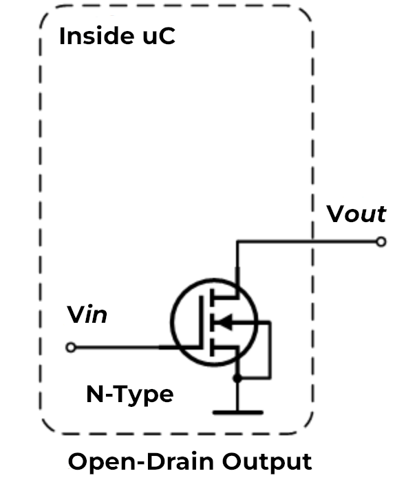
What it is: An open-drain pin is like a switch that can only connect to ground (0V) or disconnect completely. Think of it like a light switch that can only turn the light off or leave it “floating” - it cannot actively turn the light on by itself.
How it works: When the pin is active, it connects to ground (pulls the voltage down to 0V). When inactive, it simply disconnects and lets other components control the voltage on that wire.
Why it matters for 3D printers/CNC: Open-drain is useful when multiple devices need to share the same signal wire. For example:
- Multiple endstops on one pin: If you wire several endstop switches in series, they can all share one input pin using open-drain. When any switch triggers, it pulls the signal to ground.
- Shared alarm signals: When multiple devices need to signal an error condition on the same wire.
- Level shifting: When connecting 5V devices to 3.3V pins, open-drain lets you safely interface between different voltage levels.
When to use it:
Use open-drain (o) when you need to connect multiple switches or sensors to a single pin, or when interfacing with devices that expect open-collector/open-drain outputs.
Pull-Up Mode (^)
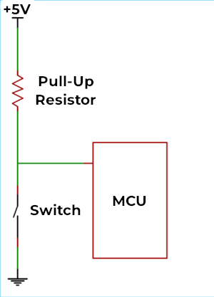
What it is: A pull-up resistor is like a weak spring that gently pulls the pin voltage up to 3.3V when nothing else is controlling it. It’s the default mode for most pins on the Smoothieboard.
How it works: Inside the microcontroller chip, there’s a resistor (typically around 50kΩ) connected between the pin and the 3.3V power supply. This resistor is “weak” - any external signal can easily override it. When you connect a switch or sensor that pulls the pin to ground, it wins over the pull-up resistor.
Why it matters for 3D printers/CNC: Pull-up mode is the standard way to connect switches and sensors:
- Endstop switches: When the switch is open (not triggered), the pull-up keeps the pin at 3.3V (high). When the switch closes, it connects the pin to ground, reading as 0V (low).
- Thermistor connections: Many temperature sensors work with pull-up resistors to create a voltage divider.
- Simple wiring: You only need two wires to your switch - one to the pin and one to ground. No separate power wire needed.
When to use it:
Use pull-up (^) for most switches, buttons, and sensors. This is the default and works for the majority of inputs on a 3D printer or CNC mill. If you don’t specify a modifier, the pin automatically uses pull-up mode.
Pull-Down Mode (v)
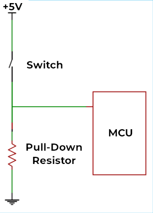
What it is: A pull-down resistor is the opposite of pull-up - it’s like a weak spring that gently pulls the pin voltage down to 0V (ground) when nothing else is controlling it.
How it works: Instead of connecting to 3.3V, the internal resistor connects between the pin and ground. The pin reads as 0V (low) by default, and only reads high (3.3V) when something actively drives it high.
Why it matters for 3D printers/CNC: Pull-down is less common but useful in specific situations:
- Active-high sensors: Some sensors output 3.3V when triggered and disconnect when not triggered. Pull-down ensures the pin reads 0V when disconnected.
- Normally-closed switches: If you’re using a switch that’s closed by default and opens when triggered, pull-down can simplify your wiring.
- Positive logic preference: When you want the pin to read “low” in the idle state and “high” when activated.
When to use it:
Use pull-down (v) when connecting sensors or switches that provide a positive voltage when active, or when you specifically want the opposite behavior of pull-up mode. This is relatively rare in typical 3D printer setups.
Repeater Mode (@)
What it is: Repeater mode is a hybrid that tries to “remember” the last signal it saw and weakly hold it there. It acts like both a pull-up and pull-down at the same time, maintaining whatever state the pin was last in.
How it works: The pin has circuitry that detects whether the last signal was high or low, then uses a weak resistor to keep it in that state. If the pin was pulled high, it acts like a pull-up. If it was pulled low, it acts like a pull-down. It “repeats” the last state it saw.
Why it matters for 3D printers/CNC: Repeater mode is useful in specific edge cases:
- Long wire runs: When you have very long cables (several meters) that might pick up electrical noise, repeater mode helps maintain signal stability.
- Floating inputs: When a pin might be disconnected temporarily but needs to maintain its last known state.
- Reducing noise: The weak holding force helps filter out brief noise spikes on the wire.
When to use it:
Use repeater mode (@) when you have long cables prone to noise, or when you need a pin to maintain its state even when the signal source briefly disconnects. This is the least commonly used mode in typical 3D printer or CNC setups - most users will never need it.
^) or pull-down (v) modes. Do not enable repeater mode simply because you think it will "make things better" - it is designed for very specific edge cases and is rarely needed in typical configurations.
Combining Multiple Modifiers
Important: You can use multiple modifiers on the same pin by placing them one after another. The pin configuration system allows you to combine different flags to achieve exactly the behavior you need.
Syntax:
my_pin_name 2.11!o^
In this example, pin
my_pin_name PC7!o^
In this example, pin PC7 is configured with:
!- Inverted outputo- Open-drain mode^- Pull-up enabled
Common Useful Combinations
Here are some practical combinations you might use in your 3D printer or CNC setup:
1. Inverted with Pull-up (!^)
endstop_pin 1.24!^
endstop_pin PA5!^
This is extremely common for endstops. The pull-up keeps the pin high (3.3V) when the switch is open, and the inversion means the firmware reads this as “not triggered.” When the switch closes, the pin goes to ground, and the inversion makes the firmware read it as “triggered.”
Why it’s useful: Many endstop configurations expect the opposite logic from what the hardware naturally provides. This lets you match your firmware expectations without rewiring.
2. Open-drain with Pull-up (o^)
shared_alarm_pin 2.11o^
shared_alarm_pin PC7o^
This creates a “wired-OR” configuration where multiple devices can signal on the same wire. Each device uses open-drain to pull the line low when active, and the pull-up resistor keeps it high when no device is signaling.
Why it’s useful: You can connect multiple safety sensors (like door switches, emergency stops, or temperature alarms) to a single pin. Any sensor triggering will pull the pin low.
3. Inverted Open-drain (!o)
output_pin 1.18!o
output_pin PB8!o
This inverts an open-drain output, which can be useful when controlling devices that expect active-high signals while using open-drain for level shifting.
Why it’s useful: When interfacing with 5V logic devices from your 3.3V Smoothieboard, you can use open-drain with a pull-up resistor to 5V on the other device. The inversion lets you maintain the expected logic levels.
4. No Pull with Invert (!-)
external_driver_pin 2.5!-
external_driver_pin PD12!-
Disables internal pull resistors and inverts the signal. This is useful when external hardware provides its own pull resistors and you need inverted logic.
Why it’s useful: Some external stepper drivers or relay boards have their own pull-up or pull-down resistors. Using - prevents conflicts between internal and external resistors, and ! adapts the logic level.
5. Pull-down with Invert (!v)
sensor_pin 1.29!v
sensor_pin PE6!v
Uses pull-down to keep the pin low by default, then inverts the reading. This means the firmware sees “high” when nothing is connected and “low” when the sensor activates and pulls the pin high.
Why it’s useful: Some active sensors output a positive voltage when triggered. Pull-down keeps noise low when disconnected, and the inversion can match your firmware’s expected logic.
Important Notes on Combining Modifiers
- Order doesn’t matter -
!o^and^o!ando!^all do the same thing - Conflicting modifiers - Don’t combine pull-up (
^) and pull-down (v) on the same pin, or pull-up (^) with no-pull (-). Only use one pull mode at a time. - Logical combinations - Think through what each modifier does and make sure they work together logically
- Test your setup - When using multiple modifiers, always test that the pin behaves as expected before relying on it for critical functions like endstops or safety sensors
Quick Reference: Common Combinations
| Combination | Config | Use Case |
|---|---|---|
| Inverted pull-up | !^ |
Endstops with reversed logic |
| Open-drain + pull-up | o^ |
Multiple sensors on one pin |
| Inverted open-drain | !o |
Level shifting with inverted logic |
| Inverted no-pull | !- |
External pull resistors with reversed logic |
| Inverted pull-down | !v |
Active-high sensors with reversed logic |
Default Pin Assignments
This table shows the default pin assignments for common functions:
| Function | Pin | Notes |
|---|---|---|
| X Step | Alpha stepper | |
| X Dir | Alpha stepper | |
| Y Step | Beta stepper | |
| Y Dir | Beta stepper | |
| Z Step | Gamma stepper | |
| Z Dir | Gamma stepper | |
| E0 Step | Delta stepper / Extruder | |
| E0 Dir | Delta stepper / Extruder | |
| Min X | X endstop | |
| Min Y | Y endstop | |
| Min Z | Z endstop | |
| Max X | X max endstop | |
| Max Y | Y max endstop | |
| Max Z | Z max endstop | |
| Hotend | PWM output | |
| Bed | PWM output |
Configuration Example
Here’s a typical configuration showing stepper and endstop pin assignments:
# Stepper and endstop configuration
alpha_step_pin                       2.0
alpha_dir_pin                        0.5!
alpha_en_pin                         0.4
alpha_min_endstop                    1.24^
alpha_max_endstop                    1.25^

beta_step_pin                        2.1
beta_dir_pin                         0.11!
beta_en_pin                          0.10
beta_min_endstop                     1.26^
beta_max_endstop                     1.27^
# Stepper and endstop configuration
alpha_step_pin                       PF0
alpha_dir_pin                        PF1!
alpha_en_pin                         PC0
alpha_min_endstop                    PG0^
alpha_max_endstop                    PG3^

beta_step_pin                        PF2
beta_dir_pin                         PF3!
beta_en_pin                          PC3
beta_min_endstop                     PG1^
beta_max_endstop                     PG4^
Summary:
- Pull-up (
^) - Default, best for switches and sensors (pin high by default, goes low when triggered) - Pull-down (
v) - Opposite of pull-up (pin low by default, goes high when triggered) - Open-drain (
o) - For sharing pins between multiple devices or level shifting - Repeater (
@) - For long cables or maintaining state (rarely needed)
Related Configuration Features
Startup Automation
Beyond the main configuration file, Smoothie also supports startup automation through the on_boot.gcode file. This allows you to automatically execute G-code commands every time your board boots up.
This is useful for:
- Automatically homing axes on startup
- Setting default temperatures or speeds
- Initializing machine state
- Running calibration routines
See the on_boot.gcode documentation for details on how to set this up.
SD Card Files
For more information about other special files on the SD card (like config-override, firmware.bin, etc.), see the SD Card documentation.
Hard setting configuration
You can do away with an editable configuration file altogether if that makes sense in your setup. For example, if you don’t want users to have an easy way to edit the configuration by editing the configuration file on the SD card.
To do this, remove the configuration file from the SD card. Then follow the instructions at Compiling Smoothie but before compiling, edit the file named “config.default” to contain the values you want. Then compile, and flash to the board.
Now the firmware will be configured with the values you set, but users won’t be able to edit them using the SD card, and modifying values will require compiling and reflashing.
This is useful for example if you are an OEM selling machines where users are not meant to play around with configuration.
Configuration Approaches
In Smoothieware V2, configuration is always file-based on the SD card (config.ini). Hardcoding configuration into the firmware is not supported. This ensures users can always modify settings on the SD card, which aligns with Smoothieware’s philosophy of accessible configuration.
If you need to restrict access to certain settings, consider using read-only file permissions on the SD card or physical access controls rather than firmware-level restrictions.